Rotational encoders are definitely a must-have even in hobby robotics. When you want an encoder in your project, you have many options:
- traditional optical encoders (IRCs) – precise, fast, not so cheap and big
- “ball-mouse like” optical encoders – cheap, fast, reasonably big, poor resolution
- magnetic encoders – small, wonderful resolution, not so fast and expensive
- etc.
With two projects in my mind (one really up budget, the second one requiring really small and really fast (>100kHz) encoders) I thought: why not to build a capacitive encoder? Basically a variable capacitor whose capacitance determines the position. It could be cheap (etched on a PCB) and really fast. So I decided to explore possibilities of this approach.
Overview
As usual, I started with an overview of existing solutions. Surprisingly, it is hard to find any reasonable resources. I found only two types of existing projects – professional solutions without any documentation for scientific purposes and a really nasty hobby projects which are far-far away from any reasonable results. There was only one exception – Elm Chan’s laser projector, which uses a capacitive encoder for galvanometer feedback.
In his project, he uses a diode bridge and a high frequency AC voltage (>8 MHz) to measure a capacity difference of two capacitors. The circuit should produce a small voltage on a output proportional to the difference. However, I wasn’t able to reproduce his results. My circuit produced a lot of noise and was practically useless. Clearly I am not an analog guy. So I decided to do it in more digital way.
First prototype
The idea is simple – I create a plate capacitor with half-circle electrodes by etching a pattern on main PCB and on a small PCB carried by motor shaft. Then I use the 555 timer in an astable configuration with the plate capacitor for timing. The circuit will produce a square-wave signal with a period proportional to the overlap of the electrodes and therefore, proportional to the shaft position. The frequency can be measured using a timer on a MCU in the input-capture mode. Simple, right?
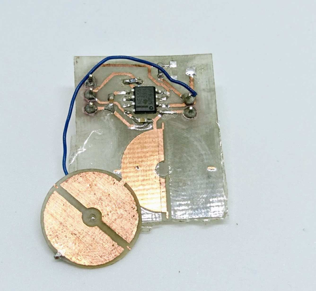
After designing a simple PCB, which you can find here, I etched it and populated it. To protect the electrodes from a short and also to create as small spacing as possible (to increase capacity) I covered one of the electrodes with a transparent tape. The diameter of the semicircles is 15 mm (and therefore the active area is roughly 88 mm2. Based on resistor values I used, and the frequency I obtained, the capacity of this capacitor is about 8 pF – 5 times more then I expected (the tape is probably a better dielectric then I expected).
The first tests looked promising – I was able to measure a position, however the whole system was quite noisy and especially sensitive to touch – and mechanical stress. This is probably due to movement of the plates – event they lie on a the tape, if you squeeze them a little, they move closer together and it leads to big increase in the capacity. I also think this setup is quite sensitive to air humidity and temperature. Also it does not allow for continuous rotation because of the wire connecting one electrode to the main PCB. I was thinking about connecting the the other electrode via the motor shaft and the motor case, however, one of my friends had a nice idea (thanks Jiří).
Second prototype
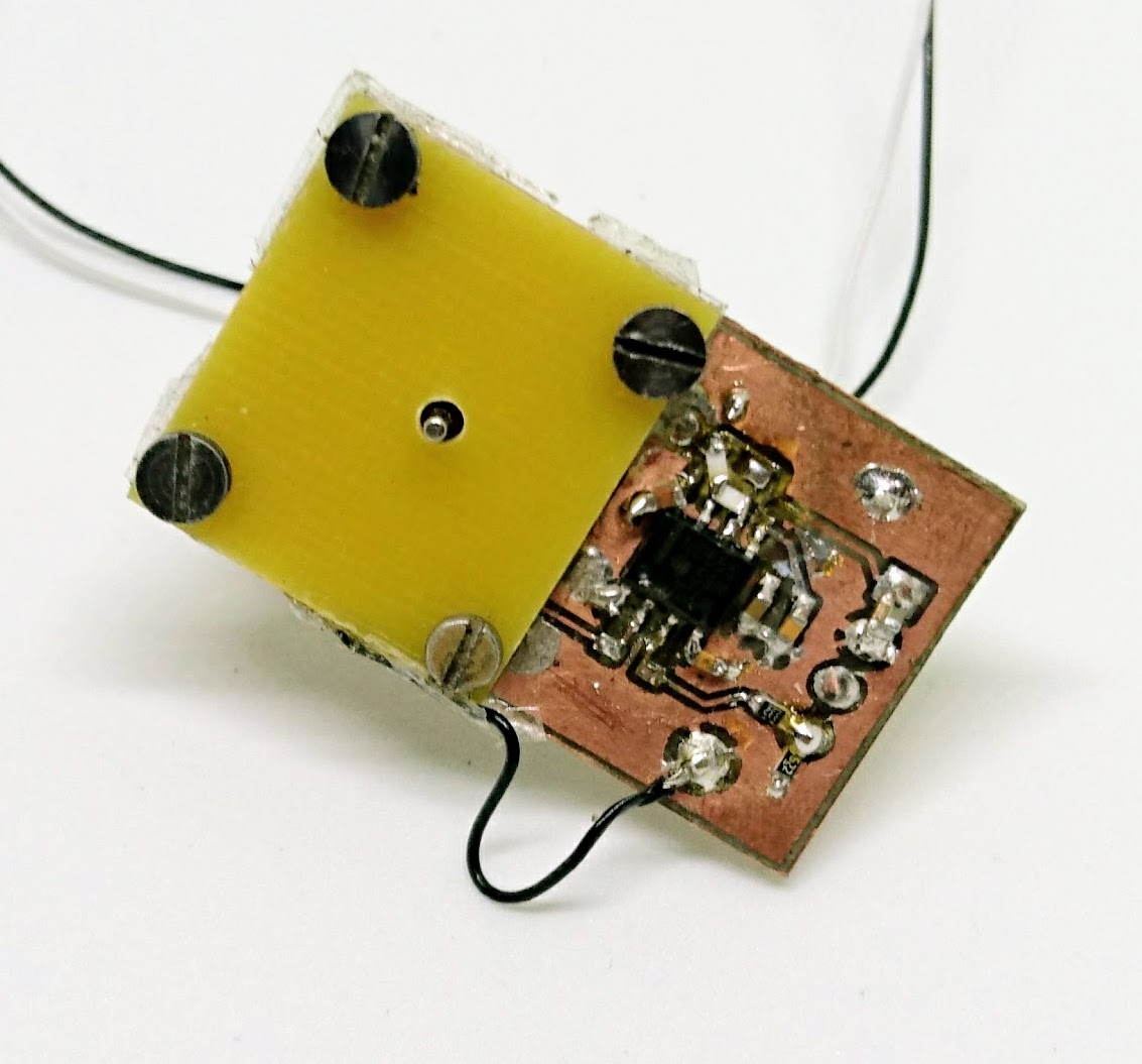
The idea behind second prototype is quite simple – do not move the electrodes, move with a semi-circle of a good dielectric material between two fixed plates. The electrodes are fixed and therefore it is easier to maintain a fixed distance between them. Also, even if the dielectric semicircle does not maintain a constant distance from the electrodes, it makes no difference as the ratio of air and dielectric is the same (and that’s what affects the capacity). For the material I used FR-4 – it is easy to get and has 4 times bigger dielectric constant than air.
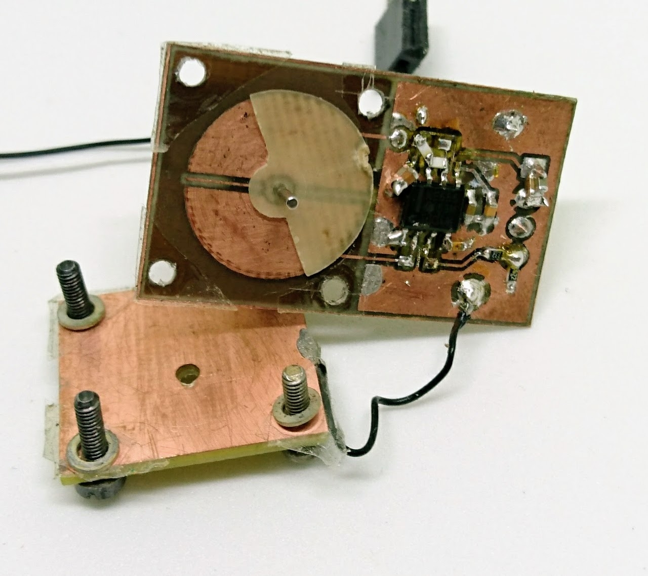
I also tried to make two electrodes for the second prototype to get rid of humidity and temperature dependency – I wanted to measure a capacity difference by measuring two capacities and making the compensation in MCU. However it wasn’t a good idea to put the two 555 timers on the other sides of PCB. Even with a decent battery of capacitors, they interfered in their function and produced an instability in the oscillation.
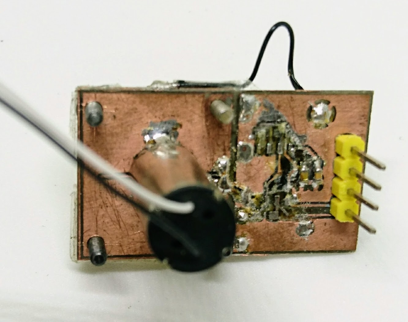
When I got rid of one of the second timer and also introduced a ground plane on the other side of the circular electrodes I was surprised with results. To test the capacitor I used ESP32 with a motor control timer in the input capture mode. This timer’s clock tick at 80 MHz and feature a 32 bit counter. First, I arranged the resistors of the 555 timer to get a frequency around 100 kHz (I was aming for really fast encoders). With this setup, the timer makes roughly 800 ticks per period. As the capacitor still has a capacity even when there is no dielectric, the low period was 720 tics and the high period was 860 period – i.e. I got resolution of 140 positions. When the encoder is stable, there is a surprisingly small noise – only +-1 tick. Also I let the encoder run for over two hours and there was no drift in the position. You might think – 140 positions isn’t much, but I can read it at 100 kHz! When I lower the frequency (or if I could get the timers in ESP32 to tick faster) I am able to increase the resolution. So basically it is a trade off between speed and resolution.
What about continuous rotation?
If you read carefully and think a little, there is one small glitch in my setup – I am only able to detect position in the range 0-180° and no more. If I continue the movement above this range, I am not able to tell if I continue or if I am returning back as the capacity decreases the same way on the both sides. There is however a simple solution, which I unfortunately haven’t tested yet.
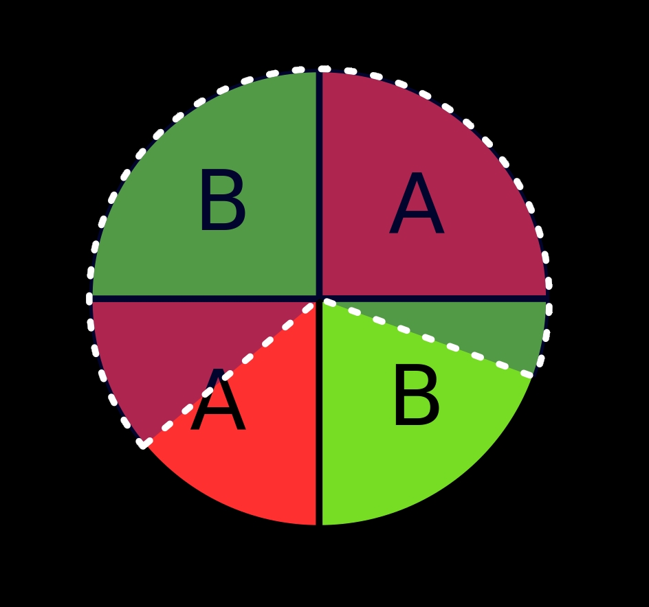
You need two electrodes A and B and a dielectric disk taking 2/3 of the full circle (semi transparent in the image). In this configuration you can always tell in which direction you move.
Conclusion
I would call my work as “proof-of-concept”. I think ultra fast capacitive encoders are feasible if you can measure period fast enough or you make Elm Chan’s circuit to work and use ADC instead. The capacitive encoder can be also a dirty-cheap solution – you need only a space on PCB, two 555 timer, 4 resistors and 4 capacitors. As the capacity of my plate capacitor is roughly 10 pF I think you could reduce its size 2 or 3 times and still get reliable results so not much of a space is necessary.
But always remember – time is money and an “expensive” solution in a form of a magnetic encoder IC might be in the end the cheapest solution.
Recent news: My open letter to the 3D-printing community
I love the 3D-printing community, but I think there is room for improvement. Let's get better in 2023! Read the full letter.
Support my work!
If you like my work (these blog posts, my software and CAD models) and you would like to see more posts on various topics coming, consider supporting me in various ways:
- You can become my sponsor on Github.
- If you prefer, you can also become my Patreon.
- You can buy me a coffee on Ko-fi,
- or you can buy something from my Tindie store (also see below),
- Or you can just share my work!
If you are interested in knowing what I am up to and recent sneak-peaks, consider following me on social media (Twitter, Instagram, Facebook).
My store offers
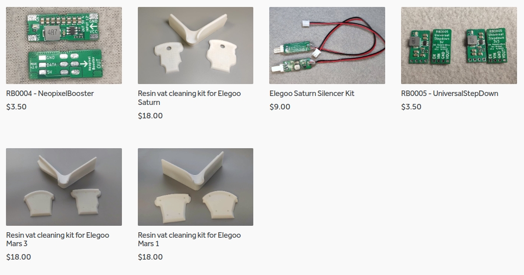
I launched new tank cleaning kits for Elegoo Saturn, Saturn S, Mars 1, and Mars 3. You can find them in my store.
Hi Jan,
Have you tried charging and measuring the capacitors directly by the MCU? Or are they too small value to be measured this way?
Can you post your schematic and the resistor values used?
I have recently made a pressure sensor based on a capacitive principle. One of the implementations I tried is with an ESP32 with built-in pull-up and pull-down resistors for a simple build without additional parts. If you use higher value, external resistors you might be able to measure pF level capacitors with just a MCU.
You can read about the build at https://blog.yavilevich.com/2017/10/40-cent-diy-pressure-sensor-based-on-a-capacitive-principle/ . If you want more details about the ESP32 variant, LMK.
I think you could, but that it would be much slower. With the current set up the MCU need one timer to count the frequency of the pulses. Measuring directly you would need a timer and an ADC read. I dont know how many sample per second you can take with on the ESP.
Unless you can read the capacitor voltage as a digital signal on an IO pin, then you would only need a timer.
Hi Thomas,
It is quite fast because it doesn’t use ADC, just digital IO. Check out the full article I linked to.
Exact timing would depend on the value of the capacitor and the resistor used.
And of course you would need to calibrate it to match readings to position.
great post about capacitive encoder !
i also made some tests using a Azoteq IC and a PCB/Electrode design like the AMT Encoder , works great in terms of resolution but is really slow (because of the IC).
Can you share the Schematic of your Design ? I think some peoples want to start tinkering around your design (included me).
You can find it here.
perfect , thanks a lot !
can you also share your Arduino code ?
I don’t have Arduino code as I needed to use the hardware timer to do input capture. However, as it was a one-time code (basically a default example for input capture), I don’t have the code anymore.
Hi Jan,
This is Rajesh from India. I have impressed with your post I tried the same experiments with your above circuit but I have not getting the capacitance change while rotating the semicircle di-electric.
Could you please post your output of this circuit & also files which you have sent to Ludwig is not opening in DesignSpark Can you please resend the files which will open in the DesignSpark.
If possible can you share your contact details.
Thanks,
Rajesh Madutha
India
Hi Rajesh,
how do you measure the capacitance? Did you try it first with an LRC meter to verify the capacitive encoder works? Could you post the schematics of your circuit?
Hi Jan,
For schematic please refer below link in that first figure, in place of ‘C’ we have put copper plate as ycapacitor.we have not check capacitor by LCR meter.
https://www.allaboutcircuits.com/tools/555-timer-astable-circuit/
we check output at pin no 3 of timer IC which gives square wave signal whose frequency depend upon ‘C’ value.
but when we rotate copper plate frequency does not change.please tell how to make capacitance variation by rotating shaft .
Regards,
Rajesh M
Here is the schematic and board I used in this project; you can check the values: https://files.honzamrazek.cz/encoderBoard.zip
Hi Jan,
I tried to open but it is showing error of failed to import from file.
can you please send image of circuit .
Regards,
Rajesh M
Here you go: https://files.honzamrazek.cz/board.pdf
That’s very cool, and simple 🙂 Perhaps you can increase the resolution via oversampling (which will use the ratio of +/-1 ticks to get better res.)