Almost all modern 3D printers, whether they use FDM or resin technology, work by creating thin layers of material and stacking them on top of each other to build a model. These layers are created by slicing the input model into horizontal, parallel planes, a process known as planar slicing. This method has several benefits, including simplicity in printer construction and a lack of collision concerns during the slicing process. FDM printers only need three axes of motion to build models using planar slicing, while resin printers only require one axis. While planar slicing has come a long way and has been greatly improved over the years, thanks in part to software such as Cura and Prusa Slicer, it does have some limitations, particularly when it comes to printing overhangs.
This is why people have proposed various non-planar slicing techniques to overcome these issues. These techniques pop-up more and more in the community. There are concepts of 5-axis 3D printers (such as Open 5x). However, we struggle with slicing that would unleash the full potential of such machines. People are experimenting with hand-crafted G-codes (such as those by FullControl XYZ) or with using cones or free path as the slicing geometry, for example. While these methods show promise, they still require a lot of development before they are ready for widespread use.
In this blog post, I would like to introduce (at least I hope) a new technique called “multi-planar slicing” as a possible solution to the limitations of traditional planar slicing. This method can be used with both resin and FDM 3D printers and has the potential to enable support-less resin printing of complex geometries. While this is just a concept at the moment and has not yet been implemented, I believe it could be a simpler alternative to other non-planar slicing techniques. Before diving into the implementation, however, I want to hear your thoughts on this idea.
What are the limits of conventional planar-slicing?
Planar slicing, while a useful method for 3D printing, does have some limitations. One of the main limitations is its inability to print overhangs. Overhangs are parts of a model that extend out from the main body and do not have any supporting structure beneath them. This can be a problem when printing with planar slicing, as each layer is laid down on top of the previous one, and there is nothing to support the overhang as it is being printed. As a result, the overhang may sag or collapse, leading to a poorly printed model, and as I showed in one of my previous blog posts, any overhang will have a distorted geometry – even on FDM as the material is being squeezed into the air on the overhangs.
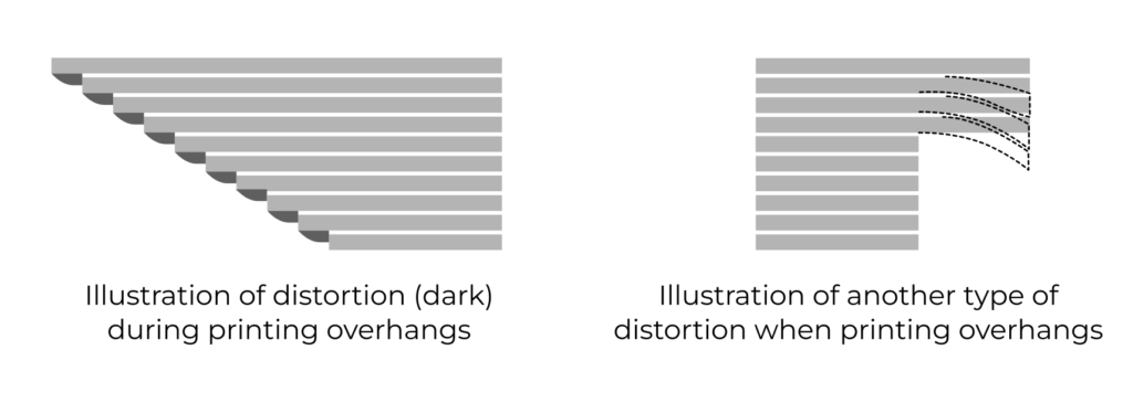
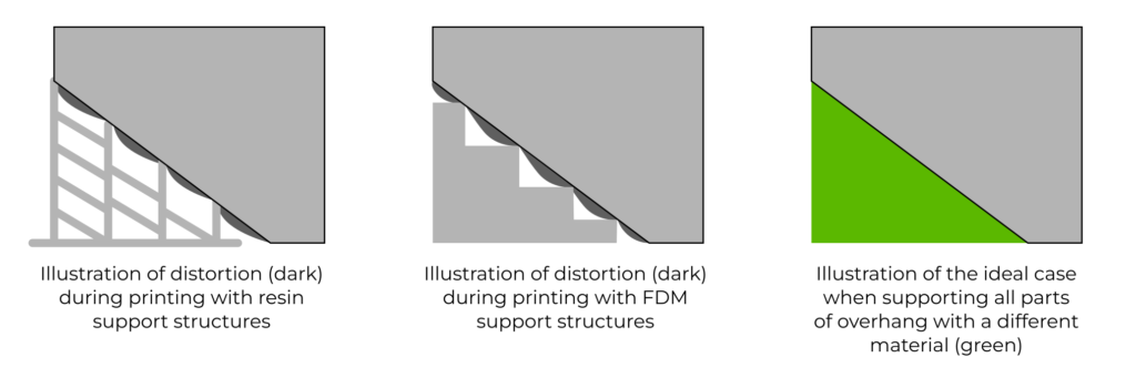
While traditional supports can be a useful workaround for printing models with overhangs, they are far from perfect. The main issue with traditional supports is that they only provide point contact with the overhanging surface of the model rather than supporting the entire surface. This results in distorted geometry of the still overhanging portion of the model and visible support marks where the support structure touches the model. In theory, the ideal solution to this problem would be to use multi-material printing, where two materials that do not bond strongly to each other are used. This would allow for the perfect support of any overhang. However, while multi-material printing is possible on FDM printers, it can be challenging, and the results are often less than ideal. On resin printers, multi-material printing is often limited to proof-of-concept demonstrations. And also, for resin printing, it is necessary for the material to somewhat bond, so the support structure survives the layer-peeling cycle.
An interesting spin on overcoming the overhangs took the belt FDM printers such as Creality CR 30. They still use planar slicing, but they don’t use a horizontal slicing plane; instead, they use a tilted slicing plane by 45° to the “natural model orientation.” As most technical models have horizontal overhangs, these overhangs are no longer overhangs under a tilted slicing plane. However, 45° surfaces instead become overhangs.
Other limitations of planar slicing include the fact that it can create visible layer lines on the finished model and may not be as effective at creating smooth, curved surfaces. A good example is an airfoil, which requires a smooth and curved surface to function correctly. With traditional methods, the surface of the airfoil may not be smooth and may have visible layer lines. However, by using a suitable non-planar slicing technique, it is possible to achieve a much better surface quality on an airfoil. See the following video for an example:
This problem is not as pronounced on resin printers due to their high resolution. Creating a smooth, tilted surface in reference to a build plate is much easier than on filament printers with the proper usage of antialiasing.
One issue specific to FDM printing is the non-isotropic strength of the finished model. The layers in an FDM-printed model do not bond perfectly, which leads to the model being stronger when the load is applied in the direction of the slicing plane rather than perpendicular to it. Some non-planar slicing techniques can address this problem by allowing the layers to be placed so that the expected load on the final model is not applied perpendicular to them. This can help improve the finished model’s overall strength and structural integrity. It is worth noting that this issue is not present in resin printing due to the different bonding properties of the layers that yield perfectly isotropic properties (same in all directions).
The beauty of automated slicing
In my view, there are two approaches to using non-planar slicing. The first approach is similar to the one used in traditional subtractive manufacturing, such as computer-aided manufacturing (CAM). In this approach, you use CAM software to create a program for the machine to follow to manufacture your part. You load the model, define the stock material and machine setup, and then apply various manufacturing strategies. You specify how each feature of the model will be manufactured, using which tools, and in what order. The CAM software then generates concrete tool paths based on your instructions. This approach allows you to control both what is being manufactured and how it is being manufactured, allowing you to utilize your expertise and knowledge of the model’s intended use to guide the process. It is simple and effective, and allows you to get the most out of your machine and available tools without requiring sophisticated algorithms or a specialized specification language for model qualities. Hence, this approach is only “computer-aided.”
On the other hand, traditional planar 3D printing tends to be more automated. With this approach, you instruct the slicer what to manufacture but do not specify how the process should be carried out. While there are parameters that can be adjusted, most users do not change them and prefer the “single-click” experience, in my observation.
Most existing non-planar slicing approaches fall into the “computer-aided” category, where you must carefully specify the slicing primitives or guide the manufacturing process in some way. While it is possible to automate these tasks, developing sophisticated algorithms may not be worth the effort to do so. Even if you could specify all the constraints on the part of automated algorithms, it may be more laborious than simply guiding the manufacturing process yourself. There is nothing inherently wrong with a computer-aided process, and it can be particularly useful for creating high-performing parts. However, I view 3D printing primarily as a rapid prototyping tool that allows for the “single-click” experience, enabling people without a background in engineering to use it easily.
In many cases, it is better to get a usable result with minimal effort than to spend a lot of time and effort fine-tuning a process to achieve excellent results. This is where 3D printing excels – it allows people to build things that they might not be able to create otherwise, either because of the small scale of the manufacturing (I make only 50 parts, and thus, I cannot afford injection molding) or a lack of expertise (I am a programmer that needs a sensor mount for a robotic project). This is why I am interested in developing slicing techniques that can be used with a single click and solve the needs of 95% of users without requiring any additional input.
Multi-planar slicing in a nutshell
Slicing a model with planes has several benefits: it is straightforward, we don’t have to care about collision avoidance, and we can already do that well with current slicers. Also, LCDs in resin printers are flat, and DLP projection works best with a plane where you can focus on.
Therefore, what if we just sliced the model with multiple planes facing various directions? In that way, we can leverage all the convenient properties of planar slicing (simple, already exists), and we gain the ability to print most models without the need for supports or overhangs. This means that models with complex geometries that would normally require support structures to be printed can be produced without them, resulting in a cleaner and more accurate final product. And most importantly, in principle, we can use it with a resin printer.
There are two more factors that we have to make. First, for practical reasons, it makes sense to restrict and allow only slicing planes that are not tilted by more than 90° from the horizontal plane. If we allowed slicing planes tilted by more than 90°, we would collide with the build plate. This might not be a problem if we, e.g., put the model on a pedestal. However, it removes the simplicity of the solution. Second, we will allow for restricting the area of the plane where we slice.
Another point of view on this strategy is to split the sliced model into multiple bodies that we sliced using the traditional approaches; each part of the original model is just sliced under a different orientation.
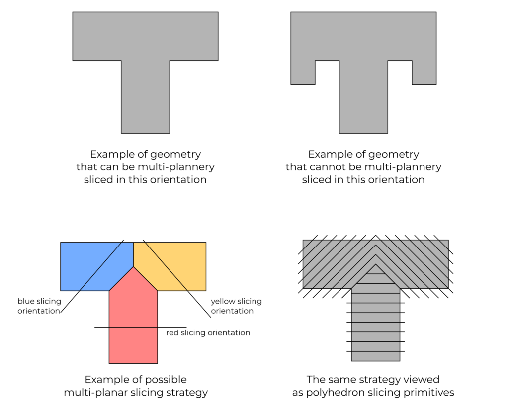
Multi-planar slicing can also be perceived as non-planar slicing with convex half-polyhedrons as the slice geometry, where we print one face at a time. Note that this is only another point of view on the same process, which might be a suitable abstraction to understand the properties of the process. Convexity of the polyhedrons is essential as it ensures collision-free paths for FDM and the possibility of sticking the printed model against the bottom of the resin tank on a resin printer. Also, the order of faces doesn’t matter with convex slicing polyhedrons. Note that the polyhedrons don’t have to be regular or symmetrically placed on the model. It is also possible to not use a fixed set of slicing directions. Instead, we can change them mid-print to best fit the model, as long as the consecutive slicing polyhedra do not intersect and do not violate the constraint of maximal layer thickness. Note that we don’t put any constraints on how thin the layer can be – actually, allowing for overlapping faces of the consecutive polyhedrons is essential.
What’s best is that I believe the whole process is fully automatable.
- Not only is there an algorithm to decide if the model can be sliced overhang-free in a given orientation, but also,
- there exists an algorithm that decides if there is an orientation in which the model can be sliced overhang-free.
- On top of that, it is algorithmically possible to find the slicing polyhedron (and minimize the number of faces it has).
- All this can be parametrized by limiting the angle of polyhedron faces.
I intentionally say: “I believe.” So far, I haven’t finished a formal proof of the correctness of all these algorithms, and I struggle a little with the generalization of finding the slicing polyhedron from a 2D to a 3D case. Nevertheless, these are obstacles that I believe we can overcome with a little effort. I plan to dedicate a separate blog post to these algorithms.
There are, however, some challenges to overcome in implementing multi-planar slicing:
- Current FDM slicers generate infill structures via simple 2D pattern generators. We can no longer do this as there are multiple directions, and the infill wouldn’t be aligned properly where the two slicing planes meet. We could tweak this, but I think it would be much better to just generate the infill as a 3D geometry and slice it just like the rest of the model (just using a different strategy to fill it with a nozzle). The benefit is that with infill as geometry, we can also do infill for resin printers.
- FDM printing leaves typical layer marks on the surface of the model. I am unsure how aesthetic would a multi-planar sliced model would be. This, though, doesn’t seem like a problem for resin printers due to their resolution.
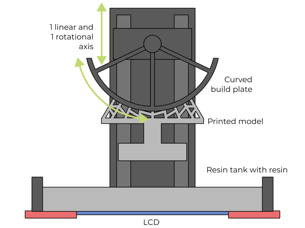
- We have to build a more complex mechanical construction for a resin printer. Instead of a single linear axis, we need to be able to rotate the build plate. Also, the build plate has to be small or curved, as we will see later in the post.
- The same applies to an FDM printer, but if we settle up for a worse surface finish and a small tilting angle of the layers, we can get away with a plain 3-axis machine (possibly with a longer nozzle, just like we see in demonstrations of conical and 5-axis slicing).
More about selecting the suitable slicing polyhedron
So far, we have assumed that we can use any slicing plane that isn’t tilted by more than 90°. However, to print with such slicing planes, we would need a proper 5-axis printer. Which makes the printer more complex and requires higher precision. It seems that we can make the following simplifications without restricting the class of printable models by one of the following modifications:
- On FDM, we could use a 3-axis printer with a long and pointy nozzle and restrict the tilt of the slicing planes to about 30° in any orientations. We also sacrifice the surface quality here as the printer will make grooves on any face that wasn’t sliced with a horizontal plane.
- We could do with just 1 rotational axis instead of two for both resin and FDM. Therefore, we allow tilt of the slicing planes only along a single axis and limit the angle to about 70° to ensure no collision with a printer head. This could restrict the class of printable models only slightly. Also, the construction of such a resin printer would be relatively simple.
Although, especially on resin printers, the rotational axe carries a heavy load (there are long levers as the model gets bigger), they are never used in a continuous mode and are only indexed. Therefore, they could feature a brake or only allow for a few orientations that are mechanically made more stable.
Possible extensions of multi-planar slicing
The whole motivation for multi-planar slicing is to avoid any overhangs. However, in practice, we don’t need a perfect surface all the time and we often prints overhangs less than 45° just fine. Therefore, if we allow small overhangs in multi-planar slicing, we can extend the class of models we can print without supporting structures. However, after a brief exploration of this topic, I can conclude that the algorithm for selecting suitable slicing planes seems to be much harder to find. But they still might exist. Similarly, we could allow for adding support structures in the direction of the tilted slicing planes.
Another extension I see is to explore printers with a single rotational axis and slicing along cylindrical surfaces. Especially with resin printers, there could be a really interesting printing arrangement: We could continuously rotate the build plate and expose only a single line of the print. Since we have a very tiny surface area, the peeling forces could be negligible; also, the sliding movement during peeling seems to yield the least peeling forces, according to Autodesk Ember. There is also enough room for resin replenishment. We can also mix the resin efficiently. Instead of LCD or expensive DLP chip, we could use a laser beam with a polygonal mirror to create the linear pattern – just like in a standard laser printer.
Final remarks
This blog post is more theoretical compared to my other ones; it doesn’t give you instant tips or uncover some interesting fact about resin printing. However, I am starting to think that it is very important to share ideas and listen to feedback. This is why put my ideas about multi-planar slicing into writing.
Multi-planar slicing isn’t the “ultimate” technique, but I think it could be a technique that is fully automatable, solves most of the use cases for printing complex geometries and it could be used with resin printers – which I find the most interesting, but I am a little bit biased as fell for resin printing in tha last years.
So why I didn’t implement this? Well, if I should follow this path, I would like to follow it with resin printers as there are already a ton of proofs of concept of non-planar printing for FDM, but none for SLA. However, implementing such approach requires a open control solution for SLA printers, not the limited boards that Chitu provides.
Nevertheless, I would like to hear your opinions and ideas in the comments!
Recent news: My open letter to the 3D-printing community
I love the 3D-printing community, but I think there is room for improvement. Let's get better in 2023! Read the full letter.
Support my work!
If you like my work (these blog posts, my software and CAD models) and you would like to see more posts on various topics coming, consider supporting me in various ways:
- You can become my sponsor on Github.
- If you prefer, you can also become my Patreon.
- You can buy me a coffee on Ko-fi,
- or you can buy something from my Tindie store (also see below),
- Or you can just share my work!
If you are interested in knowing what I am up to and recent sneak-peaks, consider following me on social media (Twitter, Instagram, Facebook).
My store offers
I launched new tank cleaning kits for Elegoo Saturn, Saturn S, Mars 1, and Mars 3. You can find them in my store.
Related Posts
- Open letter to the 3D printing community: Let’s be better in 2023! What should we do?
- Continuous Printing On LCD Resin Printer: No More Wasted Time On Peeling? Is it possible?
- About the Successful Quest For Perfect MSLA Printer UV Backlight
- Cross-layer Curing and Layer Bulging on Resin Printers: Enemy of Overall Dimensional Accuracy and Printed Threads
Maybe reach out to the NanoDLP developer about whether this could be added to NanoDLP? It’s not properly open-source but it’s a lot better than Chitu.
Very interesting.
Here’s a fun thing to test: what is the maximum layers you can afford to allow for islands? For instance, imagine an island that has no connection beneath it, but is immediately connected to a nonisland at the next layer above. That island will be hardened on the FEP (with a height beyond 1 layer due to cross layer bleeding unfortunately) where it will remain. The next cycle it may or may not be joined to the existing model, but I’m guessing if it’s only 1 layer of island and it connects somewhat significantly on the layer above, it will adhere to the print, and your model will be more accurate by not having removed that tiny island.
I don’t think it is a good idea – the resin has a maximal cure-through depth (more details in https://blog2.honzamrazek.cz/2022/01/prints-not-sticking-to-the-build-plate-layer-separation-rough-surface-on-a-resin-printer-resin-viscosity-the-common-denominator/), and thus you could make only 50-60µm islands which I don’t find particularly useful given all the risks it brings.
Yeah you’re right. Even without the cure-through issues, it’s not even going to be doing accurate curing past the first layer since the cured layer isn’t being lifted, the result being a squashed and upside-down mass on the FEP. For 1 layer, it still has potential and could add a small amount of dimensional accuracy, but beyond that you just start adding inaccuracies.
How about instead of a curved build plate, we have a moving vat and LCD assembly similar to how the Prusa SL1S functions? I imagine the complexities of manufacturing a curved build plate to be quite hard whereas for a moving assembly, we need to figure out some strain relieving methods for the LCD ribbon cable and we have to calibrate the assembly movement. The downsides to this are many as well for example, similarly to the SL1S, we either have a limit to how much resin the tank can have, have to design a special vat or have to limit the number of planes we can have. This is to prevent the resin from spilling when the vat tilts too far. Another downside is that its mechanically complex and has all the downsides of the maintenance issues that arise from that. Just throwing this idea out there, what do you think?
For the resin case, I’m not really a fan. Perhaps I’m close-minded because I’ve been trying to lock in the theory of Liquid Laminate Lithography (L^3, which includes BCN3D’s VLM) and the potential applications, but as I see it, due to the near isotropic nature of resin prints, the only benefit for non-planar for resin (that doesn’t include Duplex’s dual-planar MAP technology) is overhang support reduction.
One main strength of MSLA is the per-layer time only marginally increasing (due to suction effects) with an increasing cross sectional area of prints. Thus I mentally simulated 6 identical parts that would need overhangs to print. The simulation failed due to planar conflictions (LCD, bed and other parts) or because even more support was needed, so I reduced it to 1, negating one of MSLA’s main strengths. Even then, only under specific and very basic geometry did I get the mental simulation to pass. Due to the great resolution of resin based printers, such basic geometry would seldom be printed.
The way I want to try tackling this support problem is using less support structures (like in top-down DLP), breakaway/dissolvable supports (multimaterial), but mainly enhanced support structures such as recyclable thermoset resin…
(Slight tangent: I read about this on Fabbaloo, where the dream is to be able to turn prints straight into usable resin again with heat+chemicals, completely sidestepping the FDM requirements of having to regrind and precisely extrude new filament. Mixing resins for different properties is already standard procedure in this space and it’s much easier to tweak the colour of the output (moreso if a dark pigment is used), so it’s likely that multilple different resin prints recycled into the same liquid can still be used for prototype and dark-coloured aesthetic prints, though may have unpredictable properties. I read many of the comments on Maker’s Muse’s predictions for 2023 and many really wanted to be able to recycle their prints at home, so this could be a way to achieve this.)
…, useful support structures (e.g. Lego or Knex compatible support structures, so that the material isn’t just wasted) and magnetic pillar supports (which I’m most excited to try). I can’t see much reason why the useful support structures idea can’t be implemented in current resin printers of today, but I can only imagine the other things mentioned being doable on L^3 or PolyJet.
SLA resin printing would make a lot more sense for consumer and prosumer equipment to adopt differential support and surface curing times via grey scale curing or double layer masking / differenced double exposure. Supports for example should be cured extra hard and stiff throughout their height to maintain maximum Z-axis dimensional stiffness and stability, but at the contact point, less cured to reduce support scarring and damage. Conversely, the part or model at and around a certain radius of the support interface should be more heavily cured to prevent support deformations and reduce support removal damage.
This would enable using larger supports as well for fine details and overhangs where support contacts are often larger than the initially supported cross section and damage fine details and parts. This could also help with loss of detail in prints on the build plate facing surface as caused by support tension.
Support curing could even be geometrically optimized in 3 dimensions at the voxel level along the contact surface to promote shearing along a path which increases the preservation of detail. Consider then supports which are wide pillars which cradle along the texture of a part and preserve detail rather than adding a support scar or support protrusion at removal. Such models of course would need supports removed prior to final curing. This would be the functional equivalent of the advantages of dissolvable PVB supports in FDM. Similar approaches could also *use* suction cup forces to make a stronger during print support with less surface area attachment (there would be the tiniest bit of uncured resin / cylindrical resin trap at the interface of the middle of the support and part surface).
Further, getting into advanced grey scale and double masking / double exposure techniques would also allow slicers to pattern layers appropriately to reduce UV catalyzation of large cross sections as discussed in this article: https://blog2.honzamrazek.cz/2022/01/prints-not-sticking-to-the-build-plate-layer-separation-rough-surface-on-a-resin-printer-resin-viscosity-the-common-denominator/ This would also reduce release film adhesion, enabling faster printing by reducing over-cured large cross sections.