In the previous post, I observed squashing of the prints in the Z-direction near the build plate (roughly first 20 layers). I have discussed the problem on the Elegoo group on facebook and some of the people suggested it might be related to viscosity or surface tension of the resin itself – when a thin layer of resin forms it can either push the build platform away from the print due to viscosity or it can pull the platform closer due to the surface tension. Therefore, I run some experiments.
I appended the results of my experiments to the table starting with sample 6 (direct link to the table):
There are several interesting outcomes. First, when I introduced a 40-second delay before exposure (sample 7) I was expecting to get things better if the problem is caused by the viscosity of the resin, which is pushing the build plate away. However, I would say it had nearly the opposite effect.
So I tried the opposite – to increase the drop speed. I observed no difference in the result. It might be caused by not actually increasing the speed – there might be a software limit in the firmware and I haven’t measured the actual speed.
The last experiment is the most interesting one. I tried to print the full print bed of the material with the staircase:
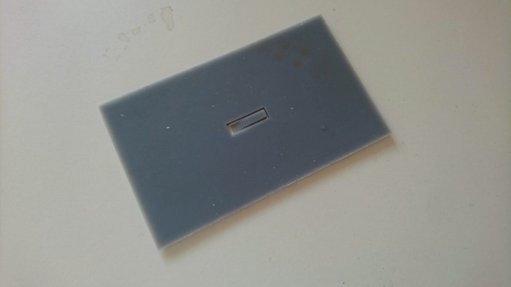
Printing the staircase with a full block all around it
The object around the staircase is only 1.5 mm tall, the staircase is 3 mm tall. The first layers of this sample (number 9) have the height of the first layers nearly good (it might be related to the precision of leveling), however, once the object ends, it gets flat. See the graphs in the table and a photo:
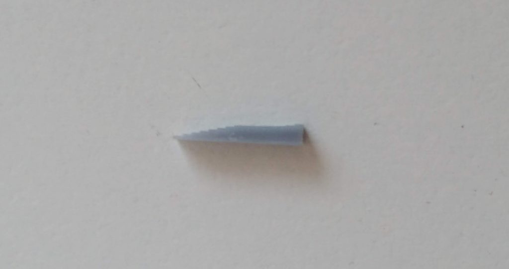
See the flat surface in the middle of the staircase
I have then tried to print just a frame around the build plate, however, the results were the same as in previous experiments. Therefore the problem is not related to the lead screw (as it happens practically on an arbitrary height) and occurs whenever a large surface area of a layer is printed. It means that printing on supports is not the solution to the problem! Imagine printing a box – when the flat bottom ends, the walls near the bottom get distorted. Tilting the prints could help, however, it requires supports and on many of my planned parts, it is undesirable to put the supports on the sides as they are functional surfaces which should not be distorted (or it might be too much work to polish them up).
Interestingly enough there is one more observation – the layer height distortion happens only when the dense layer ends – in my test case the layers between 0-1.5 mm have a rather good thickness. From the table, it seems like the effect takes place once there is a vertical gap between large surface area on a build plate and the FEP film between 0.1-0.5 mm. However, I have no explanation of the phenomenon yet. Last what I struggle with is the fact that if it would be simple FEP film deflection, it wouldn’t cause a change in the total object height. I would expect the object to have the correct height as the other layers will be a little taller. This leads me to an idea of actually losing steps on the stepper driving the Z-axis. But I have not verified yet.
Do you have some observation, ideas? Please let me know! If you try to reproduce my experiments, let me know!
Recent news: My open letter to the 3D-printing community
I love the 3D-printing community, but I think there is room for improvement. Let's get better in 2023! Read the full letter.
Support my work!
If you like my work (these blog posts, my software and CAD models) and you would like to see more posts on various topics coming, consider supporting me in various ways:
- You can become my sponsor on Github.
- If you prefer, you can also become my Patreon.
- You can buy me a coffee on Ko-fi,
- or you can buy something from my Tindie store (also see below),
- Or you can just share my work!
If you are interested in knowing what I am up to and recent sneak-peaks, consider following me on social media (Twitter, Instagram, Facebook).
My store offers
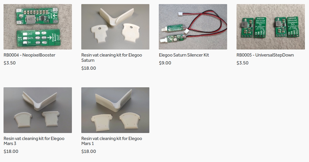
I launched new tank cleaning kits for Elegoo Saturn, Saturn S, Mars 1, and Mars 3. You can find them in my store.
Related Posts
- Multi-planar Slicing for 3D Printers – For Both FDM and Resin
- Open letter to the 3D printing community: Let’s be better in 2023! What should we do?
- Continuous Printing On LCD Resin Printer: No More Wasted Time On Peeling? Is it possible?
- About the Successful Quest For Perfect MSLA Printer UV Backlight
Hello,
have also make some experience with the Elegoo Mars 2 Pro and since few days the Saturn – Both printer have the same problem with z-Height. The Elegoo Support not understand that the problem is not the orientation of the object. I have calibrate X and Y -Axis – wrote here:
https://www.elegoomars.com/forum/showthread.php?tid=699
For both printers i can print accurate near 0,02mm in X and Y. But the Z-Height is a nightmare – have build some simple model only a plate and a cylinder on it – and the thickness of the cylinder is wrong – that is impossible if the plate is correct – it looks like some kind of backlash-problem. If i build a rook with steps around some are on the correct height and some don’t.. why this is possible? My Workaround is to print first a model and the measure the different dimensions on z-height and make some offsets on the cad-model and print again. It is not the best solution – but some other ideas to figure out the nightmare-z-axis?
Hi, Saturn has a terrible construction with a really flexible Z-axis (on the other hand it is pretty good given the price). I am investigating it, have some data but I haven’t made any conclusions, nor improvements to the printer. I would like to make a write up about my findings and measurements, however, recently I did not find enough time to dedicate to my printing hobby.
Have you experimented with exposure times as well?
I ask because fundamentally we are building object by creating mushy tiny little, partially cured 0.05 x 0.05 x (selected layer thickness) mm “bricks” of partially cured photo sensitive polymer resin (curing has been initiated but is not complete, hence the need for additional “post-process” curing) . The machine produces these bricks from beneath the final product and then alternately compresses and stretches them during the remainder of the print job.
That it works at all is somewhat of a wonder. It seems intuitive to me (and intuition is often incorrect) that some optimal initial exposure would render those “bricks” as dimensionally stable as is possible–which would have t produce a better dimensioned object.
I wanted to add FWIW i have never experienced X-Axis abberations of the magnitude you have found. Mine is a plain ol’ Mars (tag number: M20Silver20200401).