I have recently bought a new SLA printer – Elegoo Mars. For 250 € it is a wonderful device (I have to admit there are some minor flaws, but for the price).
I am interested in making precise mechanical components with it. Small teaser – you can make herringbone gears with module M0.5 or even M0.3. Wonderful. However, during my experiments, I have found a strange behavior regarding the height of the components. It seems like the first 5 layers have a wrong height. Therefore, I prepared a test piece and performed some measurements.
The test piece is simple – it is a staircase with steps of 0.2 mm in the Z-axis and 1 mm in the horizontal plane. Then I printed the piece several times and measured the height of the steps.
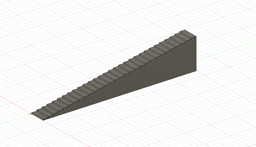
Test piece model in Fusion 360 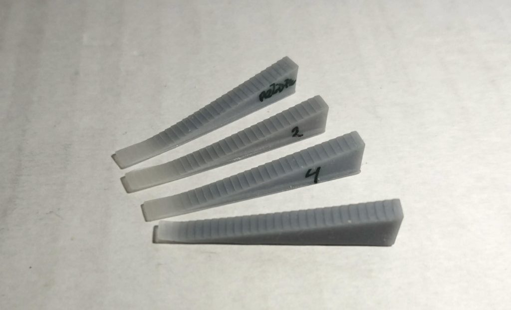
Printed test pieces
Numbers 1, 2 and 4 were printed directly on the bed. Piece number 4 was printed on supports (3 mm height). See, that pieces 1, 2 and 4 seem to have a thin beginning. My measurements confirm that (direct link to the table):
As you can see the printer is quite precise, however, there seems to be something wrong with the first 1 mm of the Z-axis – once I lift the model on the supports, the problem disappears. Note that I sanded the bottom of the lifted model, as the overhangs are always a little bit convex. I examined the sliced files with Photon File Validator and they seem fine. Therefore there has to be something wrong in the printer – either buggy firmware or hardware error.
I haven’t found the cause of the problem yet – do you have any ideas what could it cause? Does your printer feature the same behavior? Test it and let me know. Here is the Fusion model: https://a360.co/2NlHemW.
Recent news: My open letter to the 3D-printing community
I love the 3D-printing community, but I think there is room for improvement. Let's get better in 2023! Read the full letter.
Support my work!
If you like my work (these blog posts, my software and CAD models) and you would like to see more posts on various topics coming, consider supporting me in various ways:
- You can become my sponsor on Github.
- If you prefer, you can also become my Patreon.
- You can buy me a coffee on Ko-fi,
- or you can buy something from my Tindie store (also see below),
- Or you can just share my work!
If you are interested in knowing what I am up to and recent sneak-peaks, consider following me on social media (Twitter, Instagram, Facebook).
My store offers
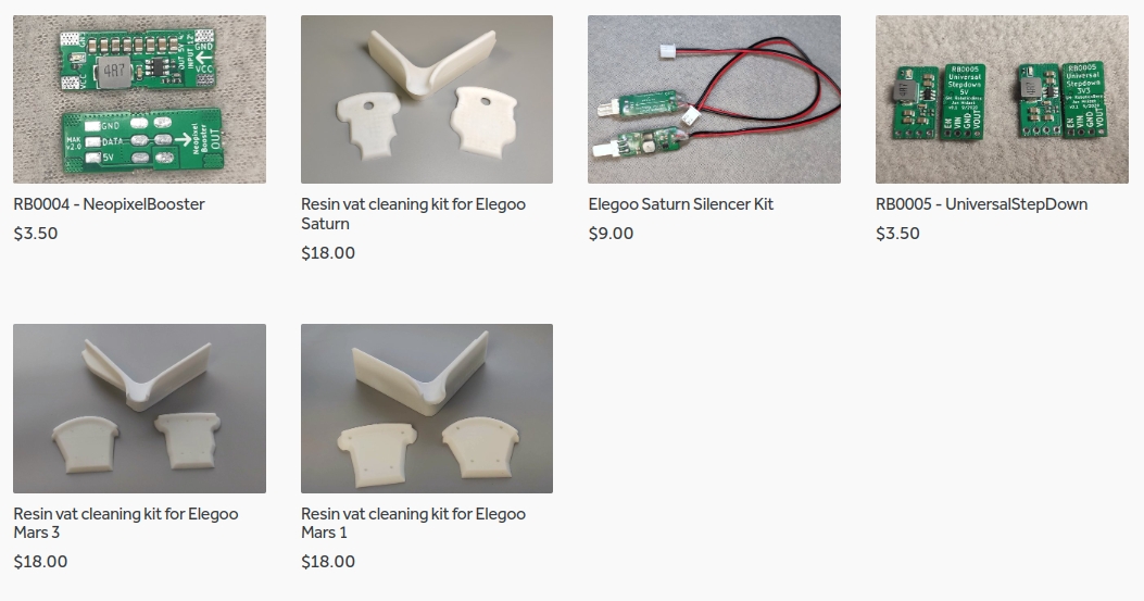
I launched new tank cleaning kits for Elegoo Saturn, Saturn S, Mars 1, and Mars 3. You can find them in my store.
Related Posts
- Multi-planar Slicing for 3D Printers – For Both FDM and Resin
- Open letter to the 3D printing community: Let’s be better in 2023! What should we do?
- Continuous Printing On LCD Resin Printer: No More Wasted Time On Peeling? Is it possible?
- About the Successful Quest For Perfect MSLA Printer UV Backlight
I have the same problem. I made a simpler test with fewer, larger steps to use as a visual thickness guide when designing objects for 3-d printing. My results were similar, but I think more erratic than yours. I solved that problem by printing the steps on their side so that the height of each step was printed in the X direction.
Today, I am having a problem printing a box and lid. They were modeled together so should fit, but because I printed them separately and I have this problem in the Z direction, the hinges do not line up.
I see that there is a “Set Z=0” button on the Elegoo Mars system screen. Have you used that? I would expect leveling the build plate to set the Z=0, but maybe not. I think I will try that next. Hopefully when you press the button, it tells you what to do to set the Z=0.
Thanks for your post–very enlightening. And I hope someone has a solution.
Unfortunately, the “Set Z=0” button is disabled – it tells you that Z=0 is automatically detected by the sensor. I have contacted Elegoo, but I have no solution (other than “use supports to print in the air”) from them yet.
I have the same problem but no solution Sad
Only I found this in the “ChiTu Mainboard SpecificationV3.0.9.gcode”
;¡¾step related parameters¡¿After the parameters are set, please print a cube, then use the ruler to measure the size to confirm that there is no problem with the parameters.
M8010 S0.000625 ; ¡¾Z mm value per step¡¿ Calculation formula: lead / ((360 / 1.8) * 16).
In englisch
I have the same problem but no solution
Only I found this in the “ChiTu Mainboard SpecificationV3.0.9.gcode”
step related parameters After the parameters are set, please print a cube, then use the ruler to measure the size to confirm that there is no problem with the parameters.
M8010 S0.000625 ; Z mm value per step, Calculation formula: lead / ((360 / 1.8) * 16).
Great article, thanks for sharing. Very interesting.
You can calibrate/config the Mars just by gcode:
1.) print test piece with known height z_t with step configuration s_0 ( in original s_t=0.000625)
2.) measure printed test peace height z_p
3.) calculate new entry s_n = s_* z_t / z_p
4.) Creation new gcode file with s_n (here written as
):M8010 S
; by test printsM8500 ; save configuration
5.) run the gcode on machine … ready
It does not solve the problem. The error is not caused by wrong steps/mm ratio. There are multiple sources of the error (at least constant + linear error) and simple 2 point calibration is not enough. Try to calibrate your printer for e.g. 20mm test piece. Calibrate it and then print e.g. 60mm test piece. It will have an incorrect height. Also, try to print a test piece with a grid pattern on a side face – you’ll see it’s distorted non-uniformly. For more information, see the continuation of this post: https://blog2.honzamrazek.cz/2019/08/testing-the-precision-of-elegoo-mars-volume-3-new-view-on-the-z-axis-problem/
ignore striking … everything was/is correct 😉
The spread sheet suggests you solved the problem. How did you solve the problem?
Read all the continuations of this post – the post no. 5 offers the solution.
Hi,
It also has an ‘x’ and ‘y’ error , but this can be corrected in drawing.
Have you checked for ‘x’ and ‘y’ accuracy ?
I have on mine and its out by 0.5%
example..
print 4 off 5mm cubes , one in each corner at spacing of 100 mm and 50 mm
After printing, DO NOT REMOVE FROM BUILD PLATE.
Now measure end to end of cubes mine were 100.52 mm and 50 .28 mm
I then went back to the original drawing and shrunk it by 0.5%
and repeated print above…
Dimensions then came out as 100.01 mm and 50.00 mm
Just got to remember to reduce drawings before making into .stl… UNLESS there is a software fix.
Obviously this is measuring on build plate and / if a complete model then shrinkage would come into play …
This is fun… isnt it !!!
Read the following:
– https://blog2.honzamrazek.cz/2019/08/testing-the-precision-of-elegoo-mars-volume-2-xy-plane/
– https://blog2.honzamrazek.cz/2019/11/getting-rid-off-the-elephant-foot-on-elegoo-mars/
– https://blog2.honzamrazek.cz/2020/01/making-elegoo-mars-more-precise-in-the-xy-direction-hardware-mitigation-of-exposure-bleeding/
Hi,
Whoops..
Must learn to read..
Been FDM for a while but new to SLA..
Sorry.
Hello. I am a complete novice with my first elegoo mars printer. I am having a huge issue with elephant foot and i read your blog about it. I downloaded the utility you made, but i have no idea how to figure out the compensation values to enter into it. Pleas explain it to me like i was a child, because i really feel kind of dumb about all of this
Rule of thumb – use 6 for the bottom layers, 0 for the other layers. Print a test piece, see if there is an elephant foot. If so, increase the value by 1 or 2 and print again. Repeat until you get the desired results.
increase both values? or just one of them?
Think. The elephant foot occurs on the bottom layers => increase only the bottom value.
also, thank you for your work and advice. I really appreciate it.