A month ago I experimented with a flexible build plate on Elegoo Mars – see the previous blog post. It gave promising results, so I decided to design it properly.
First of all – why flexible and removable build plate? There are three reasons:
you can take the sheet off, bend it at peel the prints really easily. No more spatula scraping and breaking prints from fragile materials (I am looking at you, Elegoo Standard!).
you can quickly change the sheets without the need for multiple build platforms (a platform costs around 30 €, a sheet around 2 €).
you can chapel and safely experiment with various surface finishes.
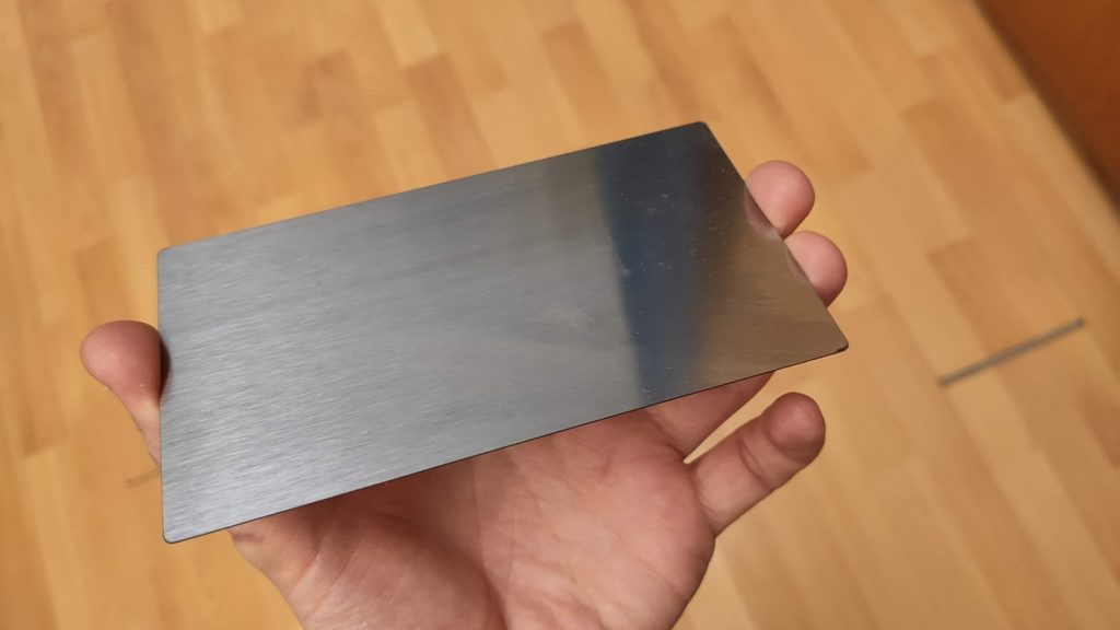
First of all, I used an ordinary galvanized steel sheet in my first experiment. It is really not suited for the task since it is soft and once you bend it stays deformed. The proper choice is the spring steel sheet – it is flat enough and you can bend it as you want. However, since it is hardened steel, you cannot machine it easily. Fortunately, there are companies laser cutting an arbitrary shape out of them on laser or water cutter. The sheets are pretty cheap to make – I made them in a small quantity and depending on the material the price for a single piece was 1-2.5€/piece including shipping. So I made the sheets 2 mm larger than the build platform with a 2mm radius on the corners. This way, there a flange you can press on to remove the sheet from the build plate.
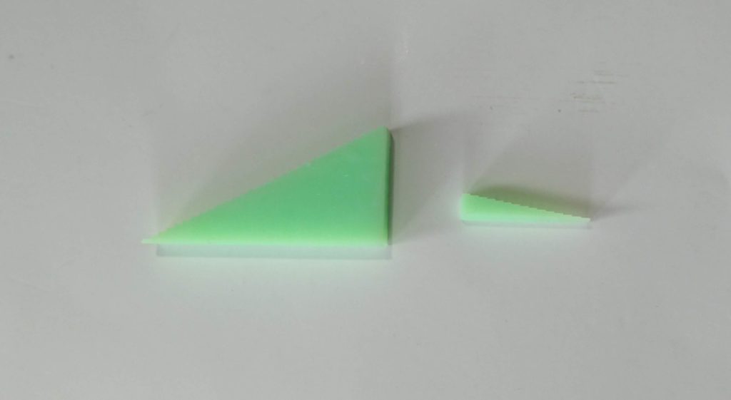
The 0.3mm spring steel sheet
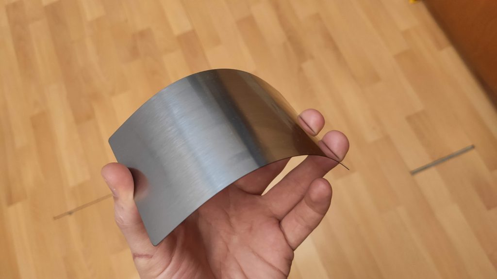
See how flexible it is.
I experimented with different thickness – 1 mm, 0.5 mm, 0.3 mm and 0.2 mm. 1 mm is practically unusable, as it is hard to bend in hand. 0.5 mm is usable, but I prefer much more 0.3 mm. 0.2 mm is my choice for extremely fragile prints.
Many people report print adhesion problems on the Elegoo Mars build platform. The build platform is sand-blasted anodized aluminum. Some of them report that sanding of the build platform flat helps. I have never experienced adhesion problems; however, I also sanded my build plate to make it perfectly flat which allowed me to print PCB stencils. Since then I face another problem – my prints stick too well and it is sometimes nearly impossible to take them off the build platform undamaged.
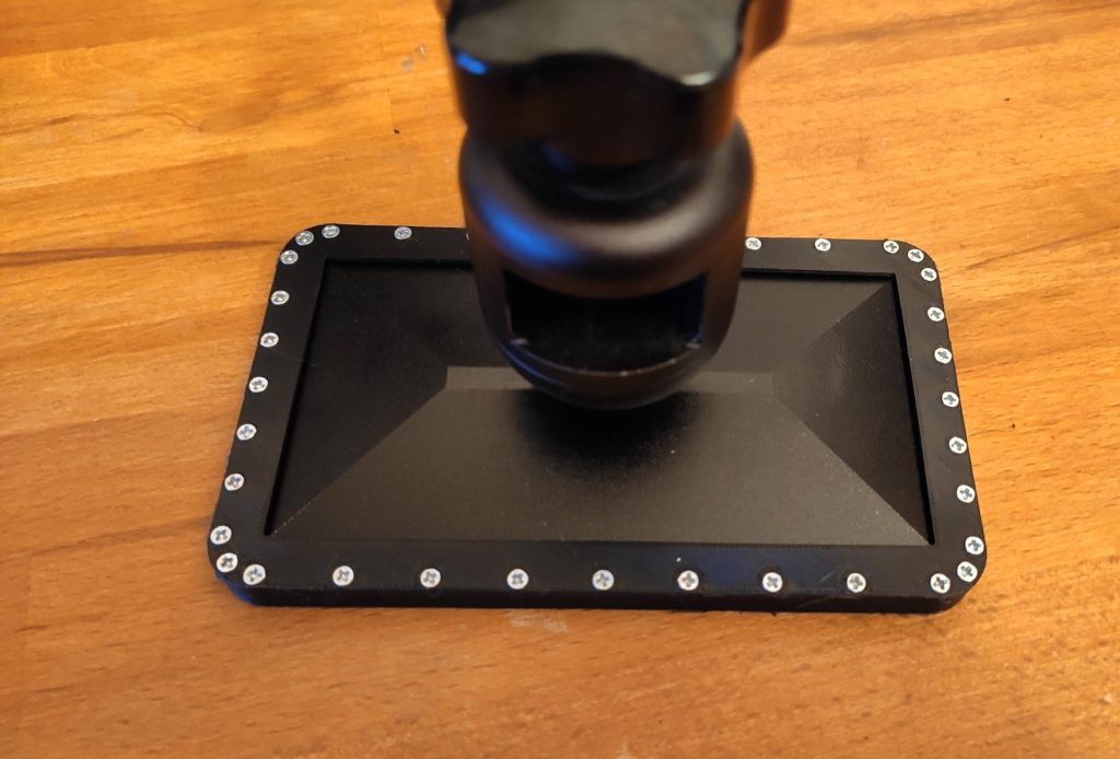
I thought; would it be possible to mimic what Prusa on FDM printers do? That is to attach a flexible steel sheet to the bottom of the platform so once you finish the print, you put the sheet down, bend it and get the prints off the build plate easily? I decided to give a shot. Note that this setup is different from other SLA machines, which claim to have a build plate attached via magnets.
So I designed a simple prototype (probably not suitable for long runs). My goals were the following: make it as simple as possible and to avoid irreversible modification of the build platform as currently, you cannot buy a spare one.
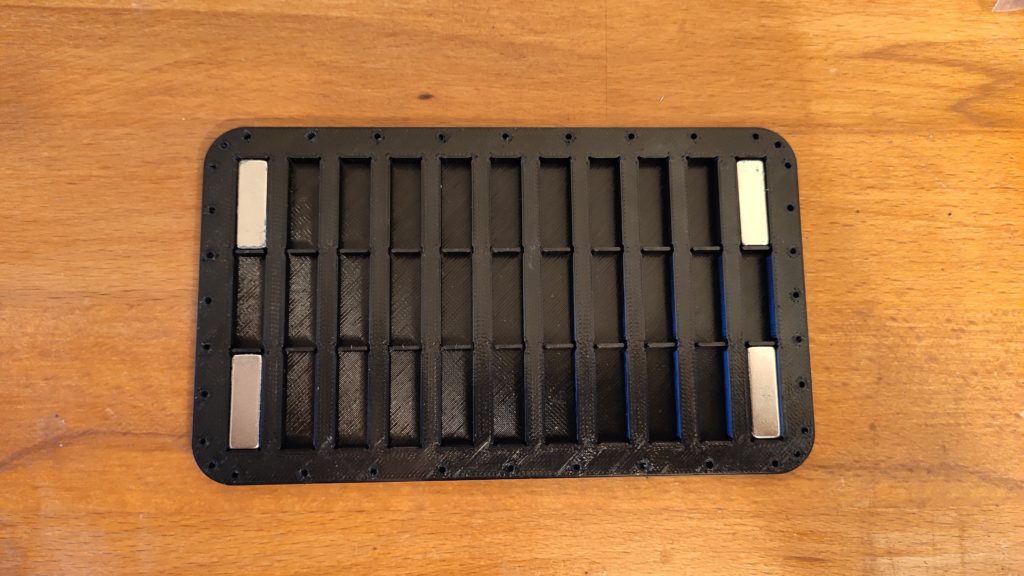
I decided to attach the sheet using neodymium magnets. I designed two simple FDM printed pieces: one plate with pockets for the magnets and one clamp to hold the plate on the bottom of the build plate. You can find my Fusion 360 drawing here.
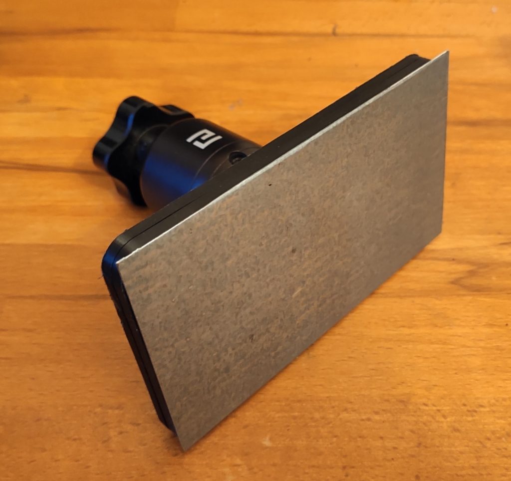
I put plenty of pockets for magnets as I wasn’t sure how many of them are really necessary to hold the sheet. I have plenty of magnets at home, unfortunately, I accidentally chose a magnet size from which I have only 4 pieces. So it broke my plans with many pockets. But I decided to give it a shot anyway with just 4 magnets. Surprisingly, the 4 magnets hold the sheet quite good (sorry, no precise measurements here). You can find pictures of the assembly below:
The LCD used for printing on Elegoo Mars is RGB – there are three subpixels – red, green and blue. Since the backlight LED produces a quite narrow range of wavelengths (peaking around 405nm), only the blue filter passes the light. That means that 2/3 of the backlight power is wasted to the LCD. Also, it means that only 1/3 of the pixel is exposed and the rest is hardened only via exposure bleeding – the effect we, on one hand, want to eliminate, on the other hand, it is essential for properly working screen. After my modification, which removed the protective glass, you can see on my prints under a microscope the effect I mentioned – 1/3 of the voxel is nice and sharp, the remaining 2/3 are smudgy.
There were recently announced printers with monochromatic LCD. They feature low exposure times (around 2 seconds) with less power than Elegoo Mars. However, their LCDs have poor resolution.
So I was wondering – would it be possible to turn Elegoo Mars LCD to a monochromatic one?
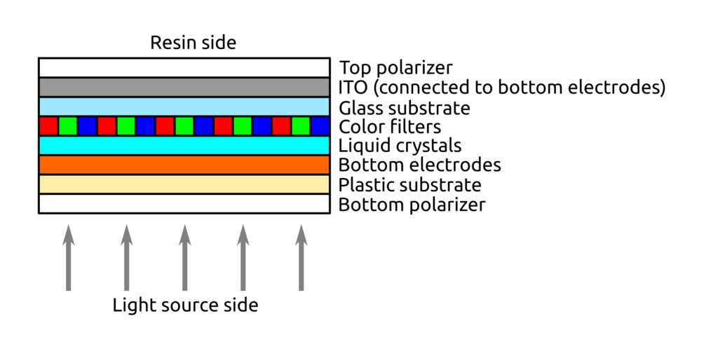
The LCD stack up
First, I examined the LCD. I figured out that the two most outer layers are the polarizer. They are not glued, they hold similarly like to protective glass. Then there is a bottom plastic film with the pixel electrodes (I am sorry for not providing pictures, however, I was not able to take them from the microscope). Then there is a glass layer – on one side (the top side) it is covered by ITO – a conductive clear coating. On the bottom side, there is a layer of color filters. Between the glass and plastic film is a layer of liquid crystals, more specifically between the plastic film and the filters.
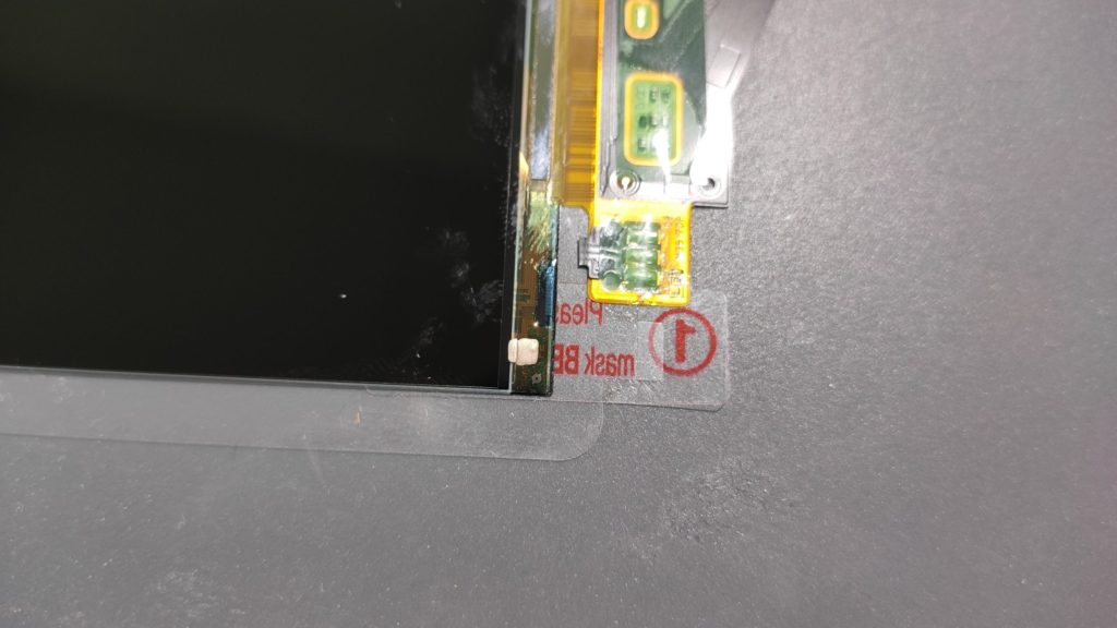
One important part – the ITO layer is connected to the plastic film via a conductive ink – see photo below.
The procedure
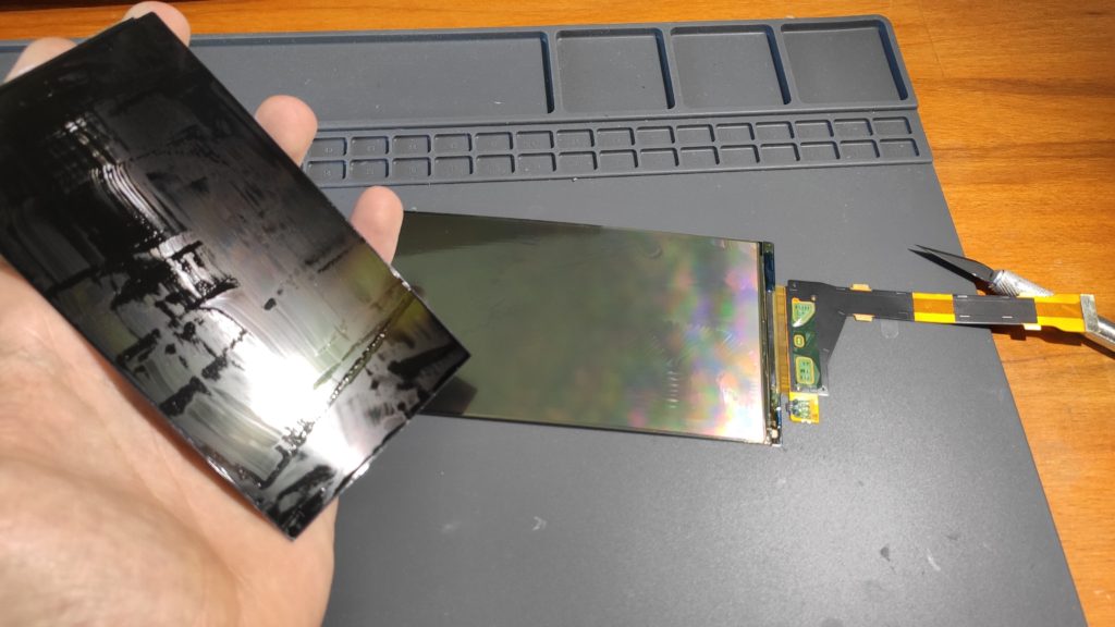
Having experiences with disassembling LCDs before, I know how to separate the glass from the plastic film. Just use a fresh Xacto knife and slide it between the layers, move along the perimeter and the layers separate:
In one of the recent posts I printer a solder paste stencil. The print is challenging as it contains small details, is thin and prints directly on the build plate. Even I use the same exposure on the first layers as did on the other layers, the first layer showed some exposure bleeding.
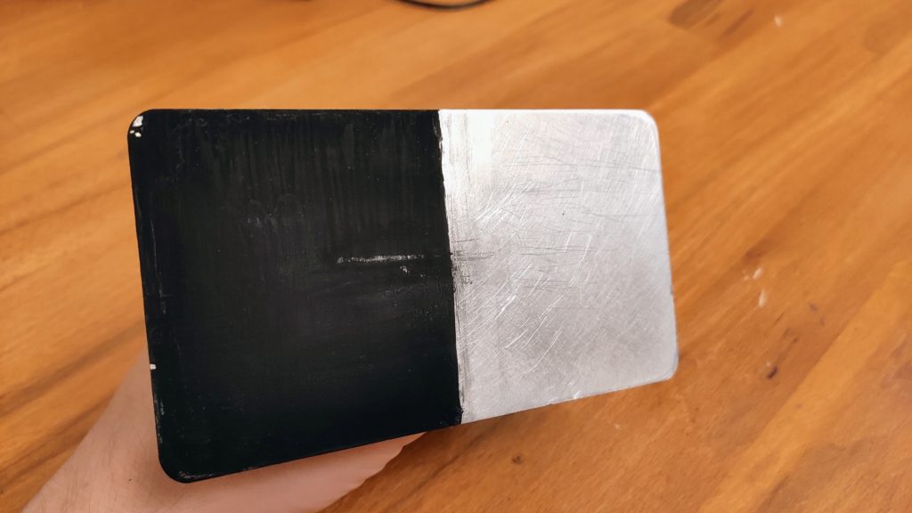
The hypothesis is that the silver surface of the build plate reflects the light, which cures the resin, and therefore more resing gets cured. I was thinking about getting really dark black paint and to paint the build plate. One of my readers, Zemerick (thank you!), brought up that Vantablack cannot be used (as it is a fragile forest of carbon nanotube), but Black 2.0 or 3.0 is just acrylic paint with a lot of pigment. So I got Black 3.0 and painted half of my build plate:
Half of the build plate painted by Black 3.0
The paint can get be scratched easily (you can see the test scratches), so I was afraid it would peel of. To my surprise – it didn’t. But the test print didn’t stick to painted plate:
A few months ago there was a tweet discussing printing solder paste stencils on a 3D printer. Someone suggested we should try it on an SLA printer. After two months I did the experiment.
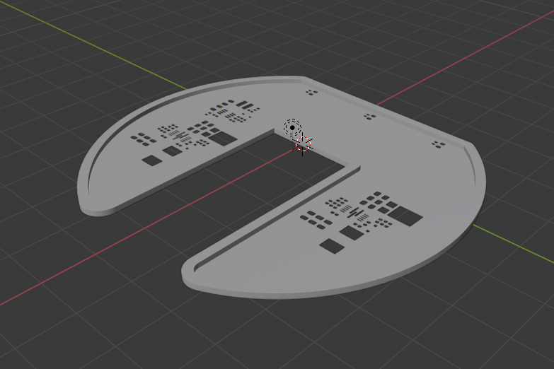
First of all, I struggled a little to get the 3D model of the stencil. There is a service https://solder-stencil.me/ which is supposed to generate the models of the stencils from gerber files. Unfortunately, when I uploaded the gerbers of my board, the model I got was completely broken. So I decided to write a custom tool. The easiest way was to use OpenSCAD (and finally an opportunity to learn it!).
So I wrote a short OpenSCAD script which takes two DXF files on the input – one for the outline and one for the holes. It also takes information on whether to generate a front or a backside stencil. You can also supply custom thickness, frame thickness, etc. If you use KiCAD I also wrote a simple Python script to export all the necessary files (which allows you to use Makefile to generate all the manufacturing data!) For the reason to me unknown, sometimes OpenSCAD produces corrupted STL files. Therefore I use admesh to post-process the STL files.
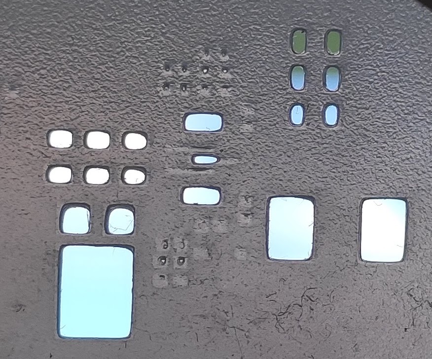
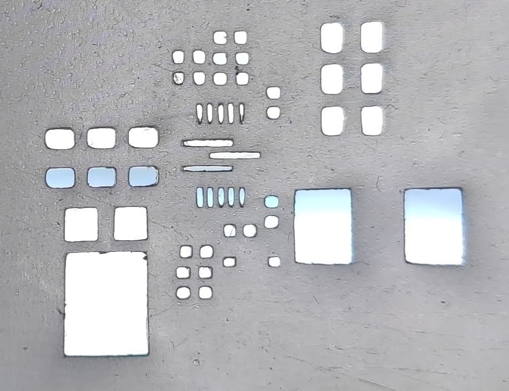
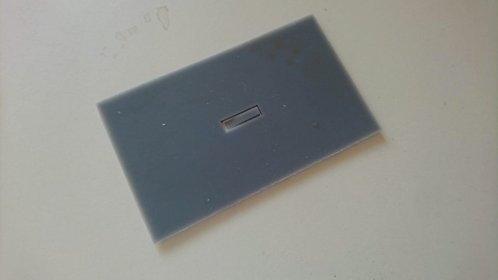
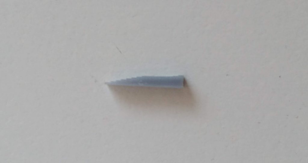
I wrote several posts on the precision of the Z-axis and gaining the precision in the XY direction on Elegoo Mars. However, last week I wanted to print models that feature narrow rectangular holes – roughly 0.2 x 0.3 mm. I thought it will be trivial – I have well explored the problem of exposure bleeding and wrote a tool for its compensation.
However, my first experiments were a complete failure. I used Elegoo standard grey and Siarya Fast grey – both without acceptable results. See the photo below (left first results, right expected results). Practically all the holes were rounded and closed in the bottom. No matter how big compensation I used, I got the same result. And when you think about it, it makes sense – the exposure bleeding rounds the sharp corners. If I compensate for it, I might get the correct dimensions of the holes, but I cannot get sharp corners.
After investigating the Z-height inaccuracy on the Elegoo Mars, and applying the official motor replacement sent to me by Elegoo (they have the best user support!) I was left with one unanswered question – what causes the last, quite small (roughly 2 %) linear error on the models’ height?
I started to measure the movement of the arm using an indicator, however, all the measurements looked good. I even measured the original screw using an optical microscope (see the raw data). It is pretty good – it features practically no jitter and only small linear error (0.2 mm/150 mm) which could be easily compensated in software.
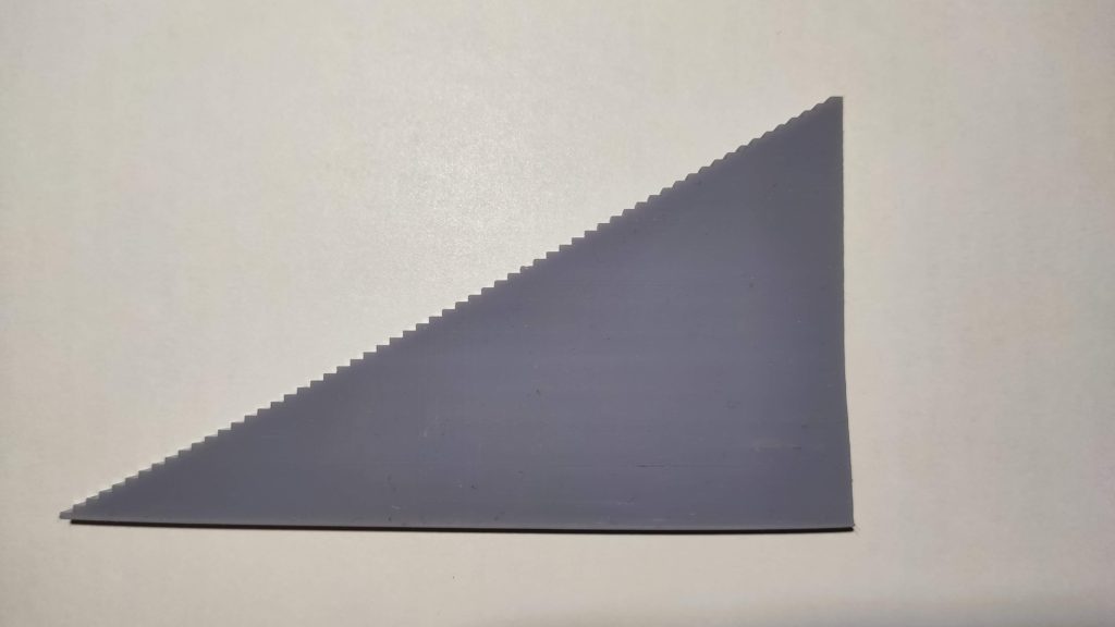
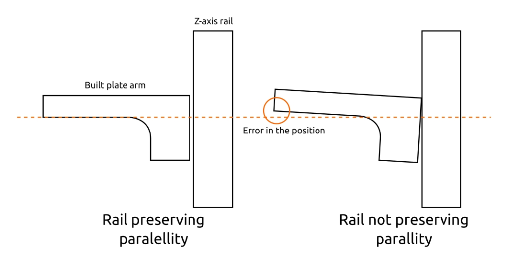
Then I printed a large staircase (see photo below) which revealed the fact I was missing – the error is not linear. The printer prints some levels higher and some lower. The cause is in the combination of the long printing arm and the Z-rail. The Z-rail provides good guidance in the direction of the axis movement, however, it does not preserve the parallelity of the carriage and the axis. It means the carriage can “wobble a little bit” during the movent which translates into an observable difference in the Z-height on the end of the long arm (see illustration below). The reason I did not get the problem with an indicator was that I was measuring too close to the screw. My bad – there’s not plenty of places you can mount the indicator on the printer and I went with the easiest one…
60 mm staircase
Illustration of the problem with the Z-axis rail
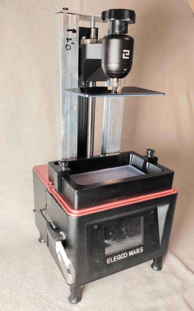
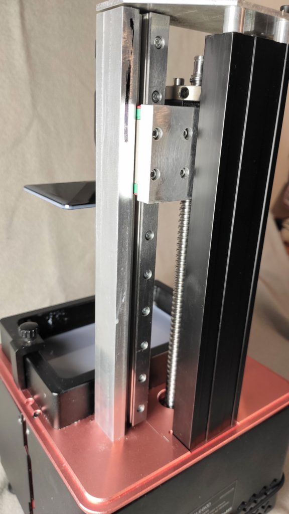
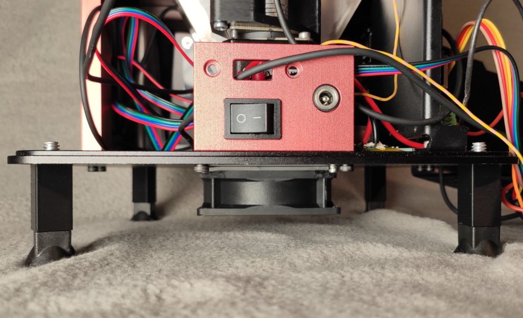
There is no easy fix, however, as tuning Elegoo Mars become my hobby in the last few months, I decided to rebuild the Z-axis. You can see the results below:
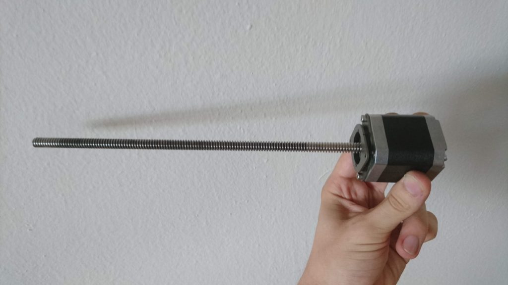
After publishing yesterday’s post I observed a strange thing – the lid of my Elegoo Mars came off during printing. The encoder I mounted on top of the Z-axis bounced it off. That was strange, how? And then it hit me. I have never, ever measured backlash of the bearings of the lead screw. I have only measured the backlash of the screw itself. Well, I think a video is worth more than a thousand words:
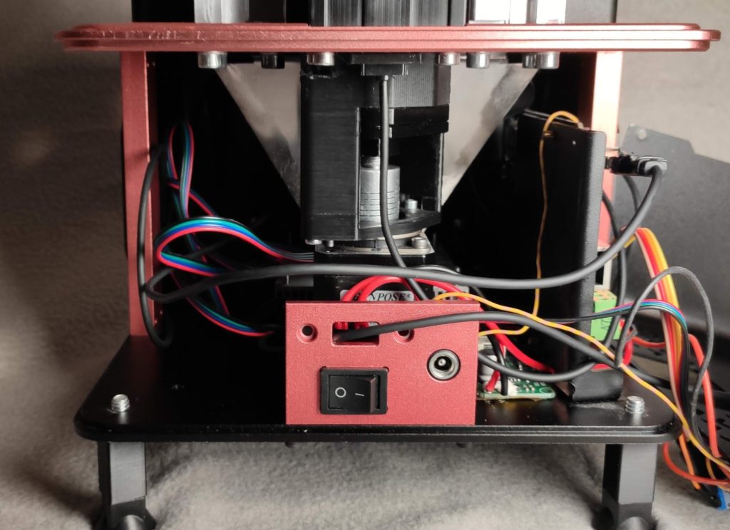
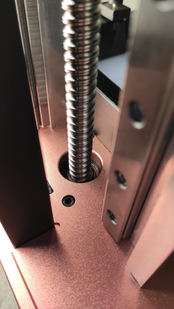
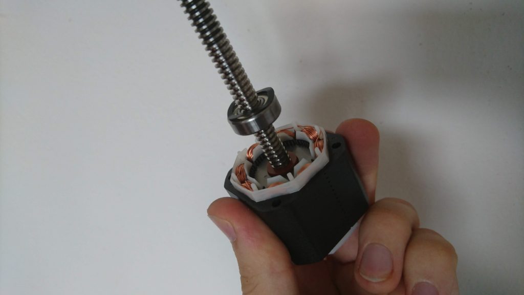
There is a play roughly 2 mm in the housing of the lead screw! I disassembled the printer:
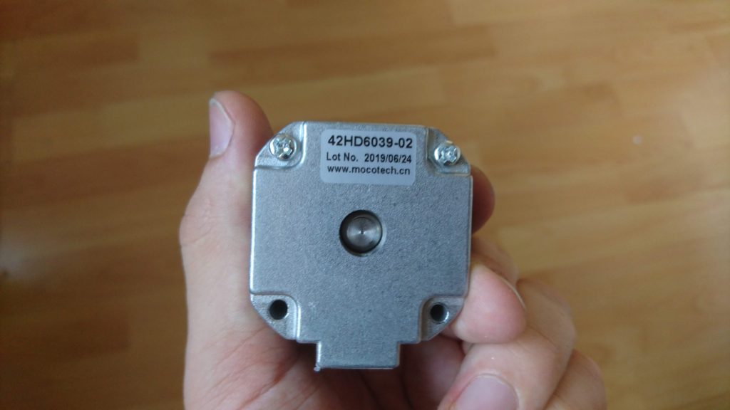
The screw servers as the shaft of the motor.
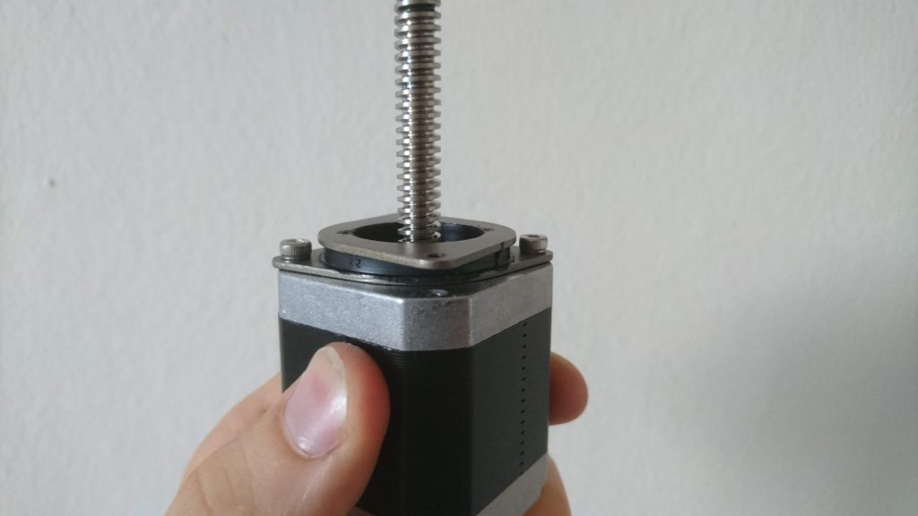
The motor is mounted on a silent block.
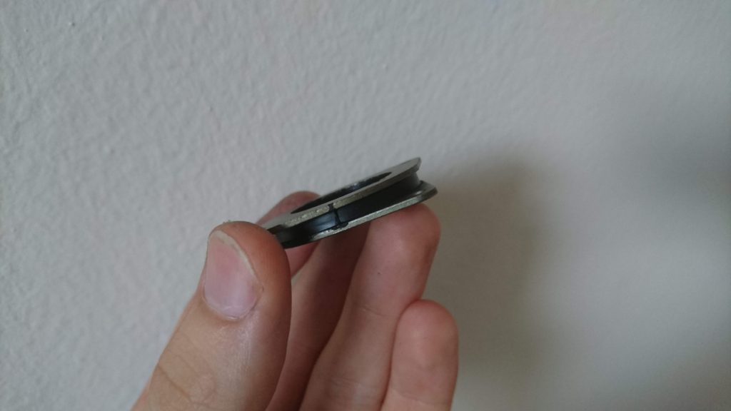
See that the essential part of the silent block is a rubber.
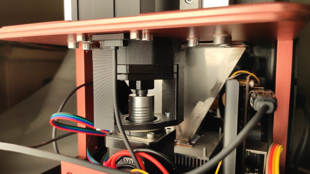
The silent block
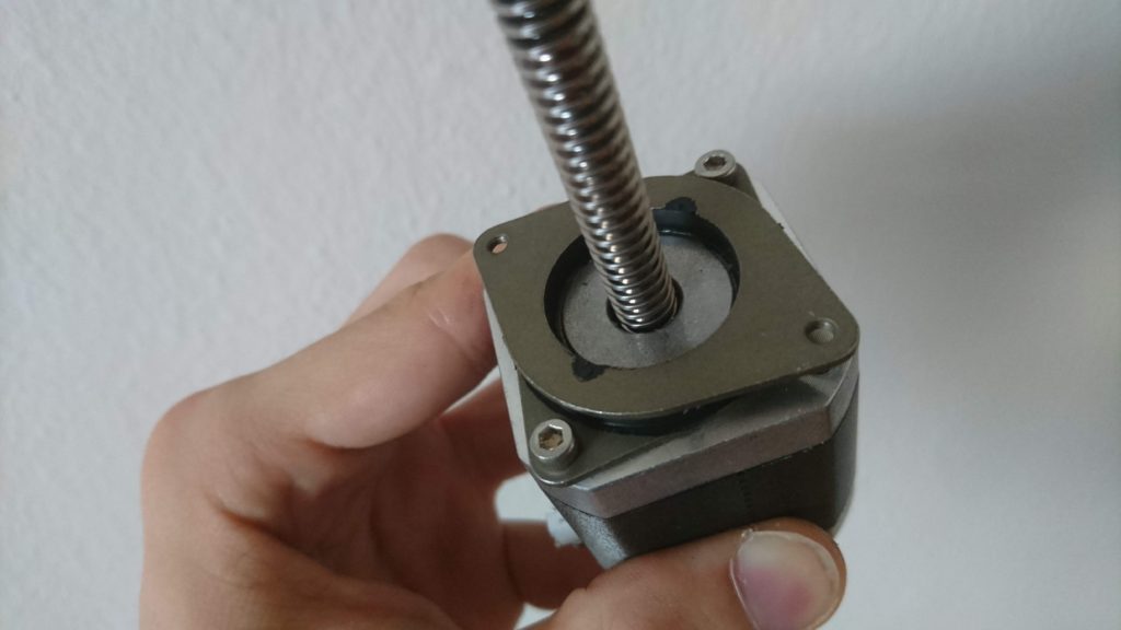
Motor caption
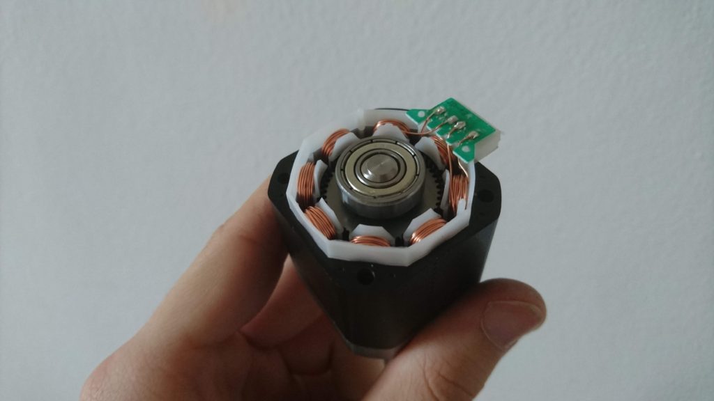
Bearing on the back side of the motor
Spacer below the bearing
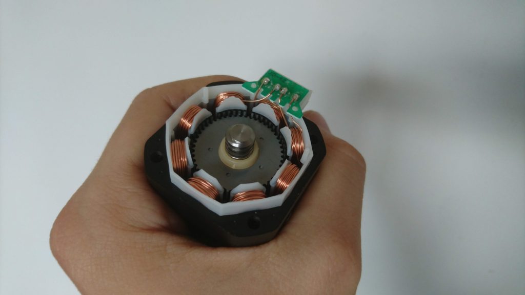
Bearing on the bottom side of the motor – see the spring washer
The cause is clear – even the motor has a lead screw as shaft and therefore, you would assume it is designed for axial load, it is not. There are ordinary ball bearings (no axial nor angle contact bearings) and most importantly – there is a spring washer tensioning the bearings – just like in an ordinary stepper designed for purely radial load. This is, in my opinion, a clear failure of the motor manufacturer MOCOC TECH. Also, there is another source of problems – the silencer – as the screw is mounted in the motor and the rubber silencer is soft. The silencer probably prevents from resonating with the top plate of the printer and also creates a flexible element which can compensate for the axial misalignment of the screw and the nut.
When you combine this flexible play in the screw with my observation about forces present during printing, you get imprecise print height – up to the size of the play of the screw. It can shrink or squeeze your layers arbitrarily.
What is the solution? There are three solutions in my mind:
dirty & cheap – get two M8 washers, put them in the motor’s rotor, remove the spring washer and tightened motor body screws carefully to slightly tension the ball bearings. Also, remove the silent block. This is a solution for roughly 3 CZK. Warning: This is a dirty solution. Deep groove ball bearings are not designed for axial load nor tensioning. Also by removing the silent block, you remove flexible element which could compensate for misalignment of the screw and the nut. Your risk shorter life of the bearing, screw, and nut. On the other hand, the speeds and axial loads on Elegoo Mars are not that big, so you might be OK for years with this solution.
better solution – get a pair of axial bearings F8-19G and use them instead of the ball bearing. Pretention them either as in the previous case or with a hard spring washer.
The best solution – build separate housing for the screw with contact angle bearings and connect the motor via flexible shaft coupler. This solution provides noise reduction using the silencer. However, when you try this it might be worth it to rebuild the Z-axis to use a linear rail as the Elegoo solution of the Z-axis has a high effect-to-cost ratio, however, I can measure about 0.2 mm of play when I apply reasonable forces by hand.
As the G8-19G bearings are not available at my local store and I had to order them, I applied the dirty & cheap fix to find out what improvement can I get. Spoiler: a huge one.
I printed the test pieces from my previous posts (volume 1, volume 3, volume 4) and the problem practically disappeared. Compare the real size of the test piece before and after:
The full dataset can be found in this table (new measurements are from sample 10).
Most notably what changed is that if an error is introduced in a layer, it is compensated by the others. Therefore absolute precision is preserved. See that all the test pieces got practically the same height.
If you look at test piece 11, you’ll see it is quite distorted. It is the sample surrounded by a full plate of material. There was noticeable distortion, however, it was different compared to the previous cases. The overall test piece height was preserved, but the layers surrounded by material were a little bit higher. Just like first layers of other pieces. This is probably due to the effect I described in volume 4 (recommend reading before continuing). The effect is that the resin is viscous and as the build plate sinks, it has to push away the resin. When I introduced the delay to allow the resin to flow away and to settle the build plate in place I got much more precise pieces. On the simple pieces, even the first layers got the correct height. On the pieces with extra material, the distortion is still there, however it is much less significant. I believe by introducing even longer delay, we can get much more precise (I plan to do this experiment).
Perfect test samples.
What struggles me is that instead of 3 mm I got 2.9 mm – pretty constantly. Therefore, I printed another staircase – 0.5 mm steps, 15 mm in total height (sample 15). I also got less – 14.7 mm. Currently, I have no idea what is this caused by – it not a constant error (not coming from incorrect bed leveling) and it is too large for shrinkage (2 % – epoxy or polyurethane resins have shrinkage less than 0.5 % and I don’t expect printer resin to be that different). Maybe tensioned bearings with misaligned screws cause step loses on the stepper. I am also not sure the error is linear – I’ll have to run many more tests. Any ideas what could it be caused by?
On the topic of lost steps – before the first print I releveled the build plate. When the print started, the build platform started to move down as expected. The build plate touched the bottom of the VAT and the stepper still continued – by the sound it clearly lost some steps. I am sure I have leveled my bed correctly. I leveled it against empty VAT. Is it possible the printer FW moves the platform a little bit below the zero point to pretention the Z-Axis to mitigate the problem with flexible housing of the screw? I don’t know, but this also something I would like to explore in the future.
After all, even there are still open questions I consider my Elegoo Mars to be used as I intended when buying it – to produce precise functional mechanical components.
Since the last post I have made many more experiments regarding the Z-issue on Elegoo Mars.
First, I tried to mount an indicator to the Z-axis. I mounted it in the middle of the arm carrying the print bed and printed my test model. To analyze the results, I aimed my phone camera to the printer to capture the measurements. I performed both dry and an actual print run. You can find the whole, uncut footage of the experiment here (warning, it is really boring):
In the previous post, I observed squashing of the prints in the Z-direction near the build plate (roughly first 20 layers). I have discussed the problem on the Elegoo group on facebook and some of the people suggested it might be related to viscosity or surface tension of the resin itself – when a thin layer of resin forms it can either push the build platform away from the print due to viscosity or it can pull the platform closer due to the surface tension. Therefore, I run some experiments.
I appended the results of my experiments to the table starting with sample 6 (direct link to the table):
There are several interesting outcomes. First, when I introduced a 40-second delay before exposure (sample 7) I was expecting to get things better if the problem is caused by the viscosity of the resin, which is pushing the build plate away. However, I would say it had nearly the opposite effect.
So I tried the opposite – to increase the drop speed. I observed no difference in the result. It might be caused by not actually increasing the speed – there might be a software limit in the firmware and I haven’t measured the actual speed.
The last experiment is the most interesting one. I tried to print the full print bed of the material with the staircase:
Printing the staircase with a full block all around it
The object around the staircase is only 1.5 mm tall, the staircase is 3 mm tall. The first layers of this sample (number 9) have the height of the first layers nearly good (it might be related to the precision of leveling), however, once the object ends, it gets flat. See the graphs in the table and a photo:
See the flat surface in the middle of the staircase
I have then tried to print just a frame around the build plate, however, the results were the same as in previous experiments. Therefore the problem is not related to the lead screw (as it happens practically on an arbitrary height) and occurs whenever a large surface area of a layer is printed. It means that printing on supports is not the solution to the problem! Imagine printing a box – when the flat bottom ends, the walls near the bottom get distorted. Tilting the prints could help, however, it requires supports and on many of my planned parts, it is undesirable to put the supports on the sides as they are functional surfaces which should not be distorted (or it might be too much work to polish them up).
Interestingly enough there is one more observation – the layer height distortion happens only when the dense layer ends – in my test case the layers between 0-1.5 mm have a rather good thickness. From the table, it seems like the effect takes place once there is a vertical gap between large surface area on a build plate and the FEP film between 0.1-0.5 mm. However, I have no explanation of the phenomenon yet. Last what I struggle with is the fact that if it would be simple FEP film deflection, it wouldn’t cause a change in the total object height. I would expect the object to have the correct height as the other layers will be a little taller. This leads me to an idea of actually losing steps on the stepper driving the Z-axis. But I have not verified yet.
Do you have some observation, ideas? Please let me know! If you try to reproduce my experiments, let me know!