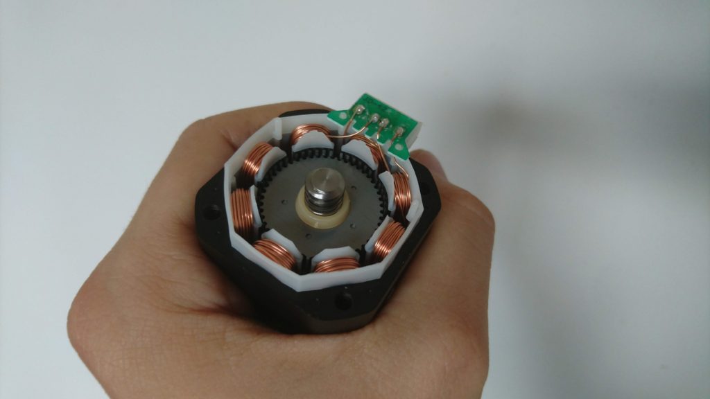
Getting Rid Off The Elephant Foot On Elegoo Mars

In one of my previous posts, I examined the XY precision of the Elegoo Mars printer. If you are not aware of the “exposure bleeding”, please read the post first. There was one problem though; ChiTuBox does not support compensation for exposure bleeding. Therefore, your models can be slightly overgrown and most importantly, when you print directly on the build plate, there is en elephant foot – the first layer are roughly by 0.1-0.4 mm larger than they are supposed to be. This is due to the long exposure period of the first layers.

I wrote a simple command-line utility, which I call ElegooMarsUtility, in September. The utility can read an already sliced file and compensate for the exposure bleeding by eroding the image (imagine removing a few pixels on the edges of white areas). You can find the utility on its GitHub page.

I posted about this utility on the Elegoo FB Group, however, people seem to struggle with the usage of command-line tools. Finally, I found a little spare time, so I programmed a simple (and probably lame) GUI for the tool, so people can use it. I hope it will do the job. It is a single form window, where you enter your compensation values in pixels, specify the input and output files and hit the run button. After a while (depending on the size of the input file) you get a compensated file.

If you use Windows, you can download the utility here, if you use Pip. Unfortunately, the Windows version is bloated and takes few seconds to start, however, there is not much I can do about it – it is the price for having a single executable. If you install the tool on Windows using Pip, the startup will be instant.

Also, if you like the tool (or my other work) consider supporting me on Ko-FI. Supporting me allows me to buy hardware and resing which goes into my research and experiments.

Most importantly; the utility works with the anti-aliased files (thanks to fookatchu and his wonderful library for handling the sliced files) and allows you to specify compensation for the bottom layers and the normal layers. This allows you to get rid of the elephant’s foot.

What compensation values you should put in? It depends on your resin and exposure time. The best way is to experiment. Personally, for Elegoo Gray I use an exposure of 8 seconds, bottom layer exposure 30 seconds, the bottom layer compensation is 6 and the normal layer compensation is 1.

One last think about the compensation. Currently, the tool compensates only for exposure bleeding. However, there could be also an error caused by the UV-light rays not exposing the resing perpendicular to the build plate, but under a slight angle (as the light source is more a point than a surface). I was not able to measure the impact of this effect on the size of the components – in theory, the worst-case scenario is that the error is 0.02 mm on the sides (based on the light source geometry and the layer thickness). The error depends on the position of the object on a build plate – objects placed in the middle are effected less than the objects on the sides. If it proofs that this error is significant, I will implement it into the tool. However, as we are dealing with compensation less than a pixel, it requires some experimenting with partial exposure.
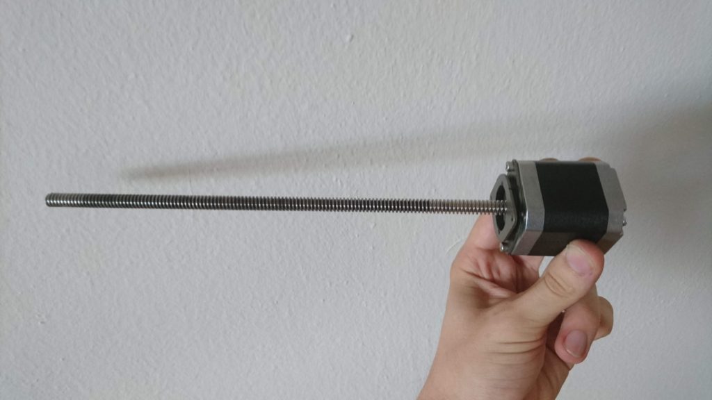
Testing the precision of Elegoo Mars – Volume 5: What’s wrong with the Z-axis and how to fix it? (finally)

After publishing yesterday’s post I observed a strange thing – the lid of my Elegoo Mars came off during printing. The encoder I mounted on top of the Z-axis bounced it off. That was strange, how? And then it hit me. I have never, ever measured backlash of the bearings of the lead screw. I have only measured the backlash of the screw itself. Well, I think a video is worth more than a thousand words:

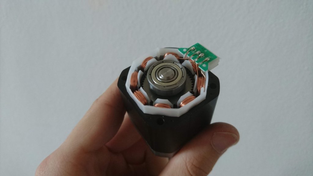
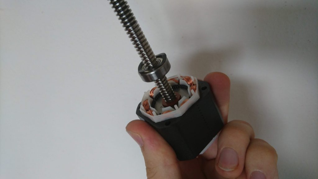
There is a play roughly 2 mm in the housing of the lead screw! I disassembled the printer:

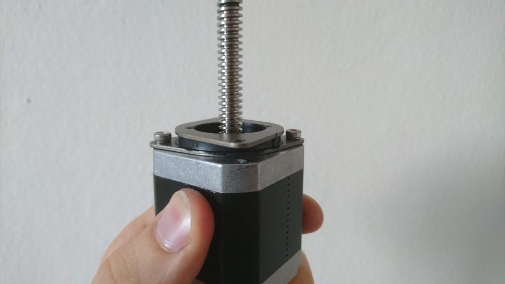
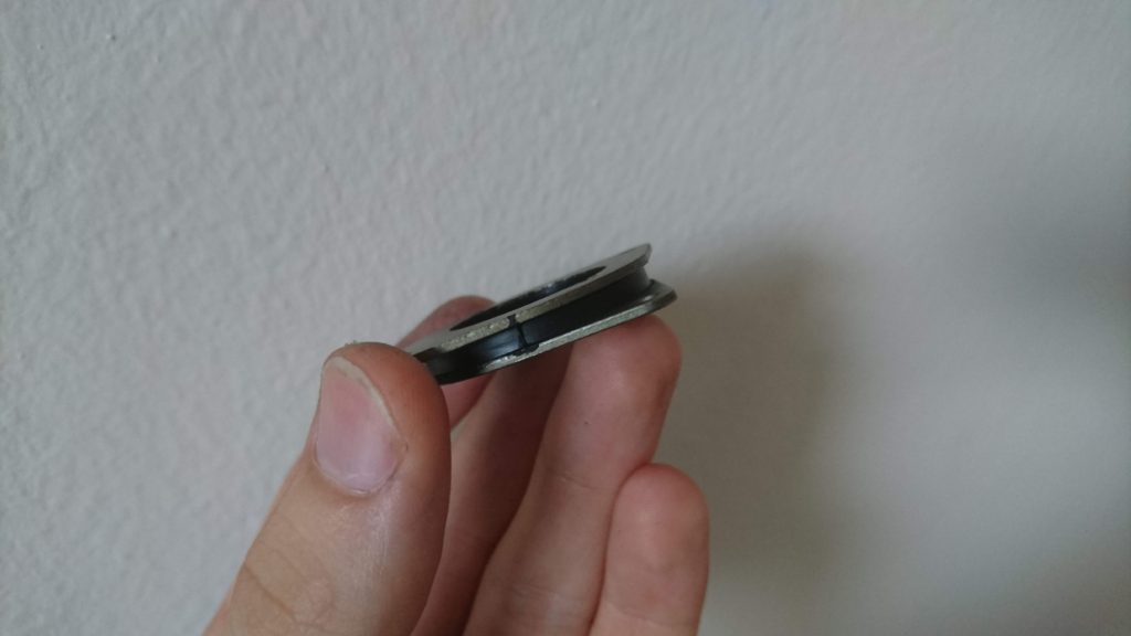
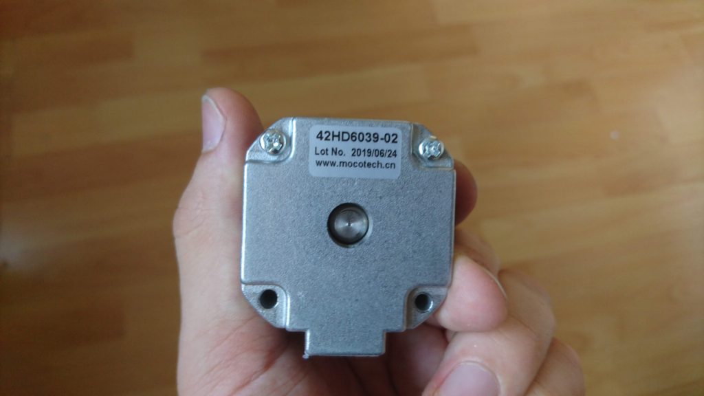
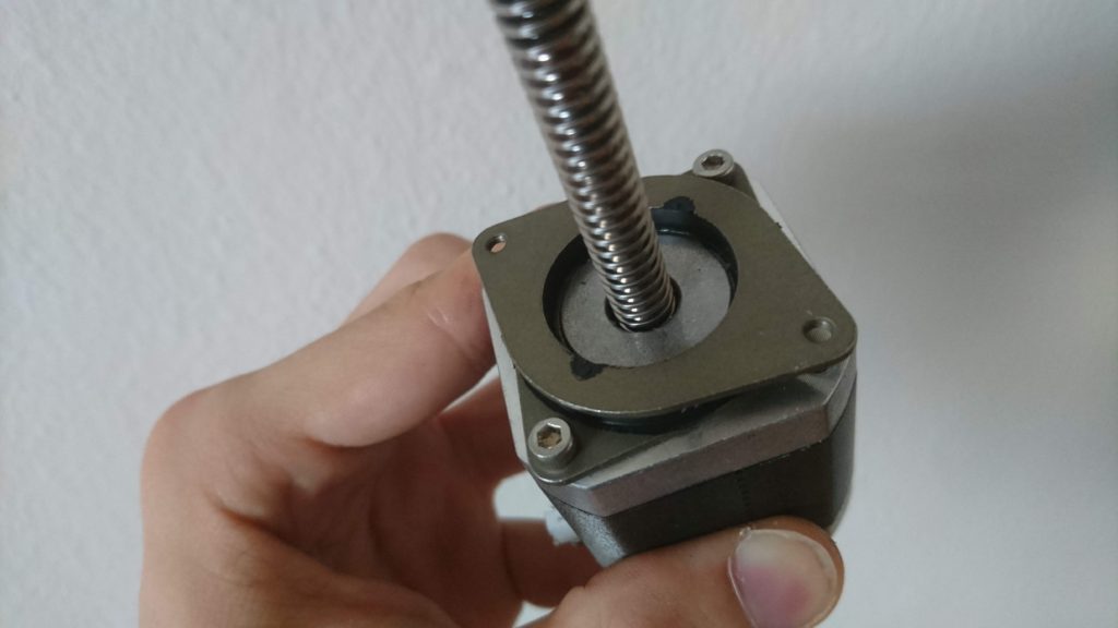
The cause is clear – even the motor has a lead screw as shaft and therefore, you would assume it is designed for axial load, it is not. There are ordinary ball bearings (no axial nor angle contact bearings) and most importantly – there is a spring washer tensioning the bearings – just like in an ordinary stepper designed for purely radial load. This is, in my opinion, a clear failure of the motor manufacturer MOCOC TECH. Also, there is another source of problems – the silencer – as the screw is mounted in the motor and the rubber silencer is soft. The silencer probably prevents from resonating with the top plate of the printer and also creates a flexible element which can compensate for the axial misalignment of the screw and the nut.

When you combine this flexible play in the screw with my observation about forces present during printing, you get imprecise print height – up to the size of the play of the screw. It can shrink or squeeze your layers arbitrarily.

What is the solution? There are three solutions in my mind:

  • dirty & cheap – get two M8 washers, put them in the motor’s rotor, remove the spring washer and tightened motor body screws carefully to slightly tension the ball bearings. Also, remove the silent block. This is a solution for roughly 3 CZK. Warning: This is a dirty solution. Deep groove ball bearings are not designed for axial load nor tensioning. Also by removing the silent block, you remove flexible element which could compensate for misalignment of the screw and the nut. Your risk shorter life of the bearing, screw, and nut. On the other hand, the speeds and axial loads on Elegoo Mars are not that big, so you might be OK for years with this solution.
  • better solution – get a pair of axial bearings F8-19G and use them instead of the ball bearing. Pretention them either as in the previous case or with a hard spring washer.
  • The best solution – build separate housing for the screw with contact angle bearings and connect the motor via flexible shaft coupler. This solution provides noise reduction using the silencer. However, when you try this it might be worth it to rebuild the Z-axis to use a linear rail as the Elegoo solution of the Z-axis has a high effect-to-cost ratio, however, I can measure about 0.2 mm of play when I apply reasonable forces by hand.

As the G8-19G bearings are not available at my local store and I had to order them, I applied the dirty & cheap fix to find out what improvement can I get. Spoiler: a huge one.

I printed the test pieces from my previous posts (volume 1, volume 3, volume 4) and the problem practically disappeared. Compare the real size of the test piece before and after:

The full dataset can be found in this table (new measurements are from sample 10).

Most notably what changed is that if an error is introduced in a layer, it is compensated by the others. Therefore absolute precision is preserved. See that all the test pieces got practically the same height.

If you look at test piece 11, you’ll see it is quite distorted. It is the sample surrounded by a full plate of material. There was noticeable distortion, however, it was different compared to the previous cases. The overall test piece height was preserved, but the layers surrounded by material were a little bit higher. Just like first layers of other pieces. This is probably due to the effect I described in volume 4 (recommend reading before continuing). The effect is that the resin is viscous and as the build plate sinks, it has to push away the resin. When I introduced the delay to allow the resin to flow away and to settle the build plate in place I got much more precise pieces. On the simple pieces, even the first layers got the correct height. On the pieces with extra material, the distortion is still there, however it is much less significant. I believe by introducing even longer delay, we can get much more precise (I plan to do this experiment).

What struggles me is that instead of 3 mm I got 2.9 mm – pretty constantly. Therefore, I printed another staircase – 0.5 mm steps, 15 mm in total height (sample 15). I also got less – 14.7 mm. Currently, I have no idea what is this caused by – it not a constant error (not coming from incorrect bed leveling) and it is too large for shrinkage (2 % – epoxy or polyurethane resins have shrinkage less than 0.5 % and I don’t expect printer resin to be that different). Maybe tensioned bearings with misaligned screws cause step loses on the stepper. I am also not sure the error is linear – I’ll have to run many more tests. Any ideas what could it be caused by?

On the topic of lost steps – before the first print I releveled the build plate. When the print started, the build platform started to move down as expected. The build plate touched the bottom of the VAT and the stepper still continued – by the sound it clearly lost some steps. I am sure I have leveled my bed correctly. I leveled it against empty VAT. Is it possible the printer FW moves the platform a little bit below the zero point to pretention the Z-Axis to mitigate the problem with flexible housing of the screw? I don’t know, but this also something I would like to explore in the future.

After all, even there are still open questions I consider my Elegoo Mars to be used as I intended when buying it – to produce precise functional mechanical components.

Testing the precision of Elegoo Mars – Volume 4: More observation, no solutions

Since the last post I have made many more experiments regarding the Z-issue on Elegoo Mars.

First, I tried to mount an indicator to the Z-axis. I mounted it in the middle of the arm carrying the print bed and printed my test model. To analyze the results, I aimed my phone camera to the printer to capture the measurements. I performed both dry and an actual print run. You can find the whole, uncut footage of the experiment here (warning, it is really boring):

Then I took the footage and put the numbers in a table (direct link to the table):

Continue reading “Testing the precision of Elegoo Mars – Volume 4: More observation, no solutions”